Crown Macro-Tech MA-5000VZ Reference Manual
Crown macro-tech ma-5000vz: reference guide
Hide thumbs
Also See for Macro-Tech MA-5000VZ:
- Schematic diagram (10 pages) ,
- Service manual (15 pages)
Table of Contents
Advertisement
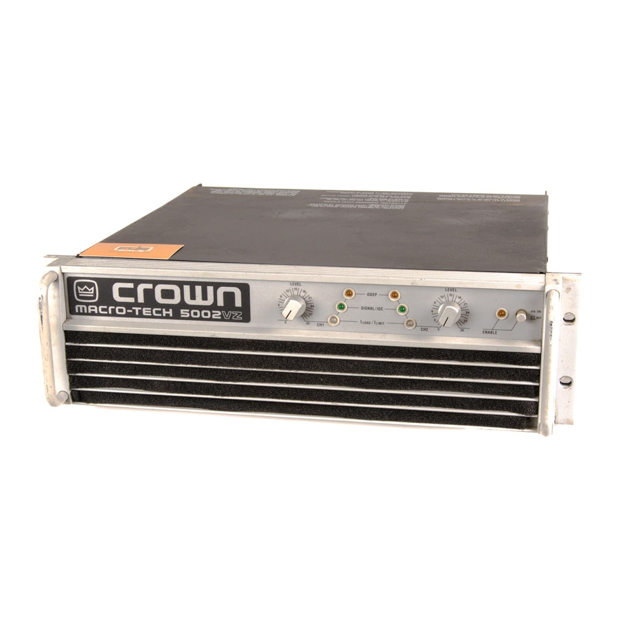
Model: Macro-Tech 5000VZ
Some models may be exported under the name Amcron.
©2003 by Crown Audio, Inc., P.O. Box 1000, Elkhart, IN 46515-1000 U.S.A. Telephone: 574-294-8000.
Fax: 574-294-8329. Trademark Notice: PIP, SmartAmp and Grounded Bridge are trademarks and
Amcron , Crown , Macro-Tech , IOC , ODEP , IQ System and P.I.P. are registered trademarks of Crown
International, Inc. Other trademarks are the property of their respective owners.
Approved for
THX Theatre
Systems
®
103169-2A
3/03
Advertisement
Table of Contents

Related Manuals for Crown Macro-Tech MA-5000VZ


Summary of Contents for Crown Macro-Tech MA-5000VZ
- Page 1 Fax: 574-294-8329. Trademark Notice: PIP, SmartAmp and Grounded Bridge are trademarks and Amcron , Crown , Macro-Tech , IOC , ODEP , IQ System and P.I.P. are registered trademarks of Crown International, Inc. Other trademarks are the property of their respective owners.
-
Page 2: North America
Warranty. ITEMS EXCLUDED FROM THIS CROWN WARRANTY This Crown Warranty is in effect only for failure of a new Crown product which occurred within the Warranty Period. It does not cover any product which has been damaged because of any intentional misuse, accident, negligence, or loss which is covered under any of your insurance contracts. -
Page 3: Important Safety Instructions
Macro-Tech 5000VZ Power Amplifier Important Safety Instructions 1) Read these instructions. 2) Keep these instructions. 3) Heed all warnings. 4) Follow all instructions. 5) Do not use this apparatus near water. 6) Clean only with a dry cloth. 7) Do not block any ventilation openings. Install in accordance with the manufacturer’s instructions. -
Page 4: Magnetic Field
Nor does it cover every possible situation which may arise during installation, operation or mainte- nance. If your unit bears the name “Amcron,” please substitute it for the name “Crown” in this manual. If you need special assistance beyond the scope of this manual, please contact our Technical Support Group. -
Page 5: Table Of Contents
1 Welcome ... 8 1.1 Why So Much Power? ... 8 1.2 Unpacking ... 8 1.3 Features ... 9 2 Facilities ... 10 3 Installation ... 13 3.1 Mounting ... 13 3.2 Cooling ... 13 3.3 Wiring ... 14 3.3.1 Stereo (Two-Channel) Operation ... 14 3.3.2 Bridge-Mono Operation ... - Page 6 Macro-Tech 5000VZ Power Amplifier 9 Service ... 43 9.1 Worldwide Service ... 43 9.2 North American Service ... 43 9.2.1 Service at a North American Service Center ... 43 9.2.2 Factory Service ... 43 Macro-Tech 5000VZ Amplifier ... 8 Front Facilities ... 10 Front Facilities behind the Filter Grille ...
-
Page 7: Welcome
Only you, the consignee, may initiate a claim for shipping damage. Crown will be happy to cooper- ate fully as needed. Save the shipping carton as evi- dence of damage for the shipper’s inspection. -
Page 8: Features
Three special modes are provided to control how and when the supplies shift impedance modes. Crown’s Grounded Bridge design delivers extreme volt- age swings without using easily stressed output transistor configurations like conventional amplifiers. The results are lower distortion and superior reliability. -
Page 9: Facilities
This is why a power sequencer is rarely needed for multiple units. (The length of the turn-on delay can be changed. Contact Crown’s Technical Support Group for details.) H. VZ Mode Switches... -
Page 10: Front Facilities Behind The Filter Grille
M. Power Cord Units configured for 100 to 120 VAC have a 10-AWG, 30-amp line cord, while units set up for 200 to 240 VAC have a 12-AWG, 20-amp line cord. North American units configured for 120 VAC, 60 Hz power are shipped with a grounded 125-volt, 30-amp NEMA TT30P plug;... -
Page 11: Rear Facilities
Your amplifier is a PIP2 amplifier, which means it can take advantage of the many ad- vanced features found in PIP2 modules. In addition, your amp can also use standard PIP modules (without the PIP2 logo). See Section 8.1 for available PIP and PIP2 modules. -
Page 12: Installation
Macro-Tech 5000VZ Power Amplifier 3 Installation 3.1 Mounting The Macro-Tech 5000VZ is designed for standard 19 inch (48.3 cm) rack mounting and “stack” mounting without a cabinet. For optimum cooling and rack sup- port, multiple units should be stacked directly on top of each other. -
Page 13: Wiring
Please use care when making connections, se- lecting signal sources and controlling the output level. The load you save may be your own! Crown assumes no liability for personal injury or damaged loads from careless amplifier use or deliberate overpowering. All units include an output cover to prevent accidental electrical shock and short circuits. -
Page 14: Bridge-Mono Operation
Macro-Tech 5000VZ Power Amplifier Note: A method for paralleling multiple amplifiers for fail-safe redundancy is available from Crown’s Techni- cal Support Group. 3.3.2 Bridge-Mono Operation Bridge-Mono mode is intended for driving loads with a total impedance of 4 ohms or more (see Section 3.3.3 if the load is less than 4 ohms). -
Page 15: Parallel-Mono Operation
3.3.3 Parallel-Mono Operation Parallel-Mono mode is intended for driving loads with a total impedance of less than 4 ohms (see Section 3.3.2 if the load is 4 ohms or greater). Installing the amplifier in Parallel-Mono mode is different from the other modes and requires special attention. -
Page 16: Input Connection
Macro-Tech 5000VZ Power Amplifier 3.3.4 Input Connection Both the XLR and ¼-inch phone jack inputs are bal- anced. They have a minimum impedance of 10 K ohms (5 K ohms with unbalanced wiring) and will accept the line-level output of most devices. The XLR connectors and phone jacks are provided on the standard PIP2-FXQ input module (other PIP and PIP2 modules are described in Section 8.1). -
Page 17: Solving Input Problems
Fig. 3.11 Input Ground Lift Switch 3.3.5 Output Connection Consider the power-handling capacity of your load be- fore connecting it to the amplifier. Crown is not liable for damage incurred at any time due to overpowering. Fusing loudspeaker lines is highly recommended (see Section 3.3.6). -
Page 18: Wire Size Nomograph
(Un- der these circumstances, Crown’s IQ System is often used so amplifiers can be easily monitored and con- trolled when they are located very near the loudspeak- ers.) In recording studios and home hi-fi, a damping... -
Page 19: Loudspeaker Fuse Nomograph
7. If the size of the cable exceeds what you want to use, (1) find a way to use shorter cables, like using an IQ System , (2) settle for a lower damping factor, or (3) use more than one cable for each line. Options 1 and 2 will require the substitution of new values for cable length or damping factor in the nomograph. -
Page 20: Ac Mains Power Requirements
The proper procedures are outlined inside the top cover of the amplifier. Contact Crown’s Technical Support Group for more information. WARNING: Risk of severe electric shock. Only a qualified technician should attempt to alter the line voltage configuration. -
Page 21: Operation
11. Tampering with the circuitry or making unau- thorized modifications can cause severe electric shock and may invalidate the war- ranty. Remember: Crown is not liable for damage or personal injury that results from overdriving system components. Page 22 Macro-Tech 5000VZ Power Amplifier 4.2 Indicators... -
Page 22: Macro-Tech 5000Vz Indicator States
Macro-Tech 5000VZ Power Amplifier Fig. 4.2 Macro-Tech 5000VZ Indicator States Reference Manual Page 23... -
Page 23: Protection Systems
Crown invented ODEP to prevent amplifier shutdown during demanding operation and to increase the effi- ciency of the output circuitry. To do this, Crown estab- lished a rigorous program to measure the safe operating area (SOA) of each output transistor before installing it in an amplifier. -
Page 24: Transformer Thermal Protection
Macro-Tech 5000VZ Power Amplifier The undervoltage protection circuitry can also acti- vate the standby mode. If the AC line voltage drops to about 20% or more below the unit’s rated voltage, both channels will go into standby to prevent loudspeaker damage that can result from brownouts and blackouts. -
Page 25: Controls
NOT protect loudspeakers from large transient voltages or excessive power levels for pro- longed periods of time. Crown cannot be held liable for damage or personal injury that results from over- driving loudspeakers or other system components. See Section 3.3.6 for information on using fuses to protect... -
Page 26: Filter Cleaning
Macro-Tech 5000VZ Power Amplifier nal (if it is turned on). If an input signal has too much voltage, the input overload circuitry will light the IOC indicator brightly, and the compressor will compress the input signal regardless of the COMPRESSOR switch position. -
Page 27: Technical Information
5.2 VZ Power VZ means Variable Impedance. It is the name of Crown’s patented articulated power supply technology. This technology is what makes it possible to pack such tremendous power into Crown’s VZ amplifiers. -
Page 28: The Vz Supply
Power Supply must dissipate. 5.2.2 The VZ Supply An articulated power supply like Crown’s VZ design can circumvent much of this problem by reducing the voltage applied to the transistors when less voltage is required. Reducing the voltage reduces the heat which makes the amplifier runs cooler. -
Page 29: Circuit Block Diagram
Macro-Tech 5000VZ Power Amplifier Fig. 5.5 Circuit Block Diagram Page 30 Reference Manual... - Page 30 The “error” amplifier (U105) is the heart of the unit. It is located in the main feedback loop and controls the per- formance of the amplifier. The error amp amplifies the difference (“error”) between the output signal and the input signal, and drives the voltage translator stage to compensate for these differences.
-
Page 31: Bridge-Mono Operation
Channel 2, twice the voltage output of a single channel is achieved. The Channel 1 output feeds the Channel 2 error amp (U205). Because there is a net inversion, the Channel 2 output is out of polarity with Channel 1. This produces twice as much voltage across the load. -
Page 32: Specifications
Macro-Tech 5000VZ Power Amplifier 6 Specifications The following applies to units in Stereo mode with 8 ohm loads and an input sensitivity of 26 dB gain unless otherwise speci- fied. All units have multitap transformers and can be config- ured for any AC line voltage. Standard 1 kHz Power: refers to maximum average power in watts at 1 kHz with 0.1% THD. - Page 33 1.4 volts for standard 1 kHz power, or a 26 dB voltage gain (see Section 4.4 for more information). Output Connectors: A multifunction, high-current output block is provided. Crown output blocks include three pairs of connectors for each channel (a total of 12 connectors). This allows multiple loudspeakers to be easily connected to each channel.
-
Page 34: Minimum Power Matrix
When measuring power, 0.1% THD appears to be the industry standard for distortion. Two of the maximum average power specifications shown in each minimum power matrix are measured at 0.1% THD so you can easily compare Crown specifications to those of other manufacturers. But this high level of distortion actually allows for some clipping which is undesirable. Because of this, a maximum average power specification at 0.05% THD is included in each minimum power matrix which represents non-clipped... -
Page 35: Maximum Power Matrix
Maximum Power Specifications Crown’s maximum power specifications represent the largest amount of output power you can expect from your amplifier when it is driven to full output under the given conditions. These specifications can be used to prevent loudspeaker and hearing damage. -
Page 36: Typical Frequency Response
Macro-Tech 5000VZ Power Amplifier Fig. 6.3 Typical Frequency Response Fig. 6.4 Typical Damping Factor Fig. 6.5 Typical Output Impedance Reference Manual Page 37... -
Page 37: Typical Phase Response
Macro-Tech 5000VZ Power Amplifier ® Measurement +45˚ 0˚ –45˚ ® 10 K 20 K FREQUENCY (Hz) Fig. 6.6 Typical Phase Response –60 ® Measurement –66 –72 –78 –84 –90 –96 ® 10 K 20 K FREQUENCY (Hz) Fig. 6.7 Typical Crosstalk Page 38 Reference Manual... -
Page 38: Ac Power Draw And Thermal Dissipation
Macro-Tech 5000VZ Power Amplifier 7 AC Power Draw and Thermal Dissipation This section provides detailed information about the amount of power and current drawn from the AC power line by the Macro-Tech 5000VZ , and the amount of heat produced under various conditions. The calculations presented here are intended to provide a realistic and reliable depiction of the amplifier. -
Page 39: Accessories
8 Accessories 8.1 PIP Modules One advantage of Macro-Tech amplifiers is the ability to customize them using PIP (Programmable Input Pro- cessor) and PIP2 modules. The MA-5000VZ amplifier is equipped with ribbon cables that will connect either directly, or via the PIP2 adapter to a PIP module. The modules install easily. - Page 40 IQ2 -compatible components like the IQ-PIP-USP2 . For more information on these or other PIPs under development, contact your local dealer or Crown’s Technical Support Group. Reference Manual P.I.P.–FMX facilitates “daisy-chaining”...
-
Page 41: Level Control Security Kit
One is needed for each channel. They can be ordered Fig. 8.2 Installing a Level Control Shaft Lock Page 42 Macro-Tech 5000VZ Power Amplifier through the Crown Service/Parts Department. For more information, contact the Crown Service Department. Reference Manual... -
Page 42: Service
Service or Technical Support to obtain prepaid ship- ping labels prior to sending the unit. Or, if you prefer, you may prepay the cost of shipping, and Crown will reimburse you. Send copies of the shipping receipts to Crown to receive reimbursement. -
Page 43: Nature Of Problem
Crown Factory Service Information Shipping Address: Crown Factory Service, 1718 W. Mishawaka Rd., Elkhart, IN 46517 Phone: 1-800-342-6939 or 1-574-294-8200 Fax: 1-574-294-8301 Owner’s Name: _________________________________________________________________________ Shipping Address: ______________________________________________________________________ Phone Number: ______________________________ Model: _________________________ Serial Number: ______________ Purchase Date: ____________ (Be sure to describe the conditions that existed when the problem occurred and what attempts were made to correct it.)
Need help?
Do you have a question about the Macro-Tech MA-5000VZ and is the answer not in the manual?
Questions and answers