Advertisement
Quick Links
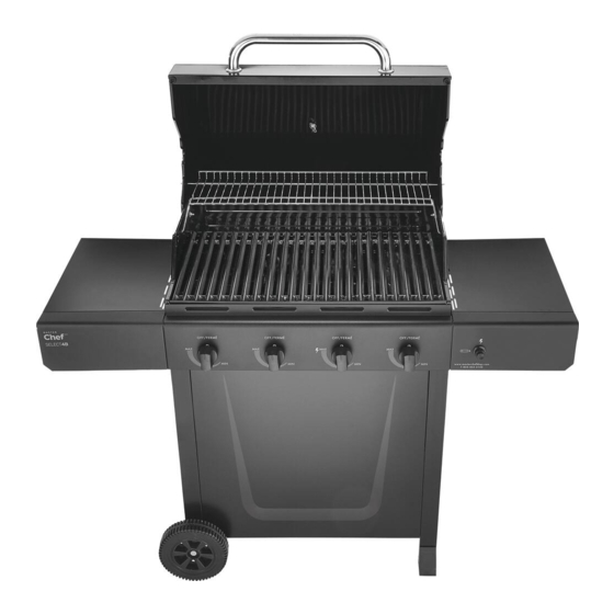
SELECT 4-BURNER
PROPANE BARBECUE
Assembly Manual
85-3064-8 (G43276) Propane
1 YEAR LIMITED WARRANTY
READ AND SAVE MANUAL FOR FUTURE REFERENCE.
Assemble your grill immediately.
Missing or damaged parts claims must be submitted within 30 days of purchase date.
For product inquiries, parts, warranty and troubleshooting support,
please call 1-855-453-2150.
ANSI Z21.58-2015 / CSA 1.6-2015
ANSI Z21.58-2015 / CSA 1.6-2015
ANSI Z21.58-2015 / CSA 1.6-2015
Manual Revision #: 02212019 JC
Advertisement

Related Manuals for Master Chef G43276


Summary of Contents for Master Chef G43276
- Page 1 SELECT 4-BURNER PROPANE BARBECUE Assembly Manual 85-3064-8 (G43276) Propane 1 YEAR LIMITED WARRANTY READ AND SAVE MANUAL FOR FUTURE REFERENCE. Assemble your grill immediately. Missing or damaged parts claims must be submitted within 30 days of purchase date. For product inquiries, parts, warranty and troubleshooting support, please call 1-855-453-2150.
- Page 2 H E A V Y A R T I C L E N E E D S 2 T O L I F T THIS MANUAL MUST REMAIN WITH THE PRODUCT AT ALL TIMES To ORDER non-warranty replacement parts or accessories, or to register your warranty, please visit us on the web at www.masterchefbbqs.com CAUTION...
-
Page 3: Tools Needed For Assembly
HARDWARE PACK TOOLS NEEDED FOR ASSEMBLY KEY # DESCRIPTION PART NUMBER QUANTITY 1/4”-20UNC X13 Screw 20120-13013-036 • #2 Star-head screwdriver (long and short) NO.10-24UNC X13 Screw 20124-10013-036 ST4.2X8 Tapping Screw 24200-42008-136 • ¼” Slotted screwdriver (long and short) Wheel Spacer G305-0024-9088 •... - Page 4 PARTS LIST PROPANE FOR 85 3064 8 G43276 KEY # QUANTITY DESCRIPTION PART NO. Top lid assembly G432-L200-01 Thermometer and bezel G312-B201-01 Lid handle brackets G352-0015-01 Top lid handle G312-B203-01 Lid bumpers-back G560-5002-01 Lid bumpers-front G527-0002-01 Screws for lid G430-0024-02...
- Page 5 EXPLODED DIAGRAM PROPANE FOR 85 3064 8 G43276 SAFETY ASSEMBLY AND CARE MANUAL MANUAL HARDWARE PACK...
- Page 6 ASSEMBLY INSTRUCTIONS a. Assemble the front panel (DD) to the left and right cart side panels (DB and DA) as shown. YOU WILL NEED: b. Ensure that the slots on the tank exclusion (DI) align with the slots on the front panel. Close Up Assemble two back braces (DC) to the left and right cart side panels (DB and DA) as shown.
- Page 7 ASSEMBLY INSTRUCTIONS Note: Turn Cart assembly upside down. a. Place wheel (DF) and wheel spacer (#4) onto the wheel axle (DG). “Cone” side of wheel should be against cart side panel, gure B. b. Insert wheel axle assembly (DG) through wheel axle hole in the front and rear of the left cart side panel (DB), as shown.
- Page 8 ASSEMBLY INSTRUCTIONS Assemble the gas tank support (DJ) to left cart side panel (DB). Note: TWO PEOPLE required for this step. Ensure that the regulator hose (CC) (Propane models only) is hanging outside of cart. Position the lid and burner box assembly (A&B), onto the cart assembly (C), and assemble.
- Page 9 ASSEMBLY INSTRUCTIONS Assemble the control knobs (CE) onto the valve stems of the manifold assembly (CB) located on the control panel (CA). RIGHT SIDE SHELF ASSEMBLY a. Assemble the hardware to the burner box assembly (BA) and control panel (CA). Do not tighten.
- Page 10 ASSEMBLY INSTRUCTIONS b. Position the right side shelf assembly (EA and EB) onto the hardware half-tightened in Step 8A, as shown in gure B and C. Right side view Back view, under right side shelf c. Tighten screws. Back view, under right side shelf d.
- Page 11 ASSEMBLY INSTRUCTIONS ELECTRONIC IGNITION ASSEMBLY a. Remove the ignition battery cover (CF2) and the plastic nut from the electronic ignition box (CF1). Battery b. Position the electronic ignition box (CF1) through the opening in the right side shelf fascia (EB) and secure using the plastic nut. Plastic Nut c.
- Page 12 ASSEMBLY INSTRUCTIONS b. Position the left side shelf (EC and ED) onto the hardware half-tightened in Step 10A, as shown in gure B and C. Left side view Back view, under left side shelf c. Tighten screws. Back view, under left side shelf d.
- Page 13 ASSEMBLY INSTRUCTIONS Place the ame tamers (BE) into the burner box assembly (BA). Close up, front view Close up, back view Place the cooking grates (BF) into the burner box assembly (BA).
- Page 14 ASSEMBLY INSTRUCTIONS To assemble the warming rack (BG), insert the stationary wire into the holes on the sides of the lid. Insert warming rack pivot legs into the holes on the inside of the burner box assembly (BA), as shown. Stationary Wire Pivot Legs Close up...
- Page 15 ASSEMBLY INSTRUCTIONS Position the 20 lb propane tank into the notches located on the bottom of the left cart side panel (DB). Position the gas tank support (DJ) onto the tank collar. Attach the regulator coupling nut (CC) to the propane tank valve. ATTENTION LP Cylinder is sold separately.
- Page 16 WARNING HOT SURFACES • CAUTION! • AVOID BURNS! • DO NOT TOUCH WHEN BBQ IS IN USE! • EXTREMELY HOT SURFACE! * SHADED AREAS BECOME EXTREMELY HOT WHEN IN USE.
- Page 17 Visit www.masterchefbbqs.com to complete product registration Master Chef® Customer Service 1-855-453-2150 Trileaf Distributions Trifeuil Toronto, Ontario M4S 2B8...
Need help?
Do you have a question about the G43276 and is the answer not in the manual?
Questions and answers