Table of Contents
Advertisement
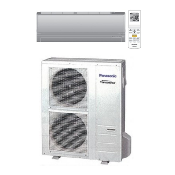
Indoor Unit
Outdoor Unit
CS-PS36RKV
CU-PS36RKV
WARNING
This service information is designed for experienced repair technicians only and is not designed for use by the general public.
It does not contain warnings or cautions to advise non-technical individuals of potential dangers in attempting to service a product.
Products powered by electricity should be serviced or repaired only by experienced professional technicians. Any attempt to
service or repair the products dealt with in this service information by anyone else could result in serious injury or death.
PRECAUTION OF LOW TEMPERATURE
In order to avoid frostbit, be assured of no refrigerant leakage during the installation or repairing of refrigerant circuit.
Advertisement
Table of Contents
Troubleshooting

Related Manuals for Panasonic CS-PS36RKV


Summary of Contents for Panasonic CS-PS36RKV
- Page 1 Indoor Unit Outdoor Unit CS-PS36RKV CU-PS36RKV WARNING This service information is designed for experienced repair technicians only and is not designed for use by the general public. It does not contain warnings or cautions to advise non-technical individuals of potential dangers in attempting to service a product.
-
Page 2: Table Of Contents
CS-PS36RKV CU-PS36RKV..... 10 14.3 Error Code Table ........39 6. Block Diagram ..........11 14.4 Troubleshooting Flowchart ......40 CS-PS36RKV CU-PS36RKV ..... 11 15. Disassembly and Assembly Instructions ..62 7. Wiring Connection Diagram ......12 15.1 CS-PS36RKV ..........62 Indoor Unit ..........12 16. -
Page 3: Safety Precautions
1. Safety Precautions • Read the following “SAFETY PRECAUTIONS” carefully before perform any servicing. • Electrical work must be installed or serviced by a licensed electrician. Be sure to use the correct rating of the power plug and main circuit for the model installed. •... - Page 4 19. During installation, before run the compressor, confirm the refrigerant pipes are fixed. Operation of compressor without fixing the piping, setting the valves at open condition, a burst may occur and cause injury. 20. During pump down operation, stop the compressor before remove the refrigerant piping. (Removal of refrigeration piping while compressor is operating and valves are opened condition will cause suck-in of air, abnormal high pressure in refrigeration cycle and result in explosion, injury etc.) 21.
-
Page 5: Specification
2. Specification CS-PS36RKV Model CU-PS36RKV IEC 60335-2-40 Single,50 / 60 Power Supply 2.50 10.55 11.14 0.92 3.06 4.00 Capacity BTU/h 8500 36000 38000 3140 10400 13600 kJ/h 9000 37980 40104 3310 11020 14400 Running Current 16.8 Input Power 3515 4200 1.17k... - Page 6 Height(I/D / O/D) mm (inch) 295 (11-5/8) / 1046 (41-3/16) 290 (11-7/16) / 542 (21-11/32) Dimension Width (I/D / O/D) mm (inch) 1160 (45-11/16) / 880 (34-21/32) 870 (34-9/32) / 780 (30-23/32) Depth (I/D / O/D) mm (inch) 255 (10-1/16) / 340 (13-13/32) 214 (8-7/16) / 289 (11-13/32) 20 (44) / 78 (172) Pipe Diameter (Liquid / Gas)
-
Page 7: Location Of Controls And Components
3. Location of Controls and Components Indoor Unit Alinium Fin Front Panel Aluminum Fin Alinium Fin Auto OFF/ON button Front Panel ・Use when remote control is Auto OFF/ON button ・Use when remote control is misplaced misplaced or a malfunction occurs or a malfunction occurs Air Filters Air Filters... -
Page 8: Dimensions
4. Dimensions Indoor Unit 4.1.1 CS-PS36RKV outlet <Remote Control> Unit:mm... -
Page 9: Outdoor Unit
Outdoor Unit 4.2.1 CU-PS36RKV Unit:mm... -
Page 10: Refrigeration Cycle Diagram
5. Refrigeration Cycle Diagram CS-PS36RKV CU-PS36RKV... -
Page 11: Block Diagram
6. Block Diagram CS-PS36RKV CU-PS36RKV... -
Page 12: Wiring Connection Diagram
7. Wiring Connection Diagram Indoor Unit 7.1.1 CS-PS36RKV REMARKS: : BLUE; P : PINK; BR : BROWN; O : ORANGE; BL : BLACK; Y : YELLOW; : WHITE; G : GREEN; : RED Y/G : YELLOW/GREEN... -
Page 13: Outdoor Unit
Outdoor Unit 7.2.1 CU-PS36RKV Resistance of Compressor Windings Resistance of Fan Motor Windings S36RKV CONNECTION 5KD240XAK21 CONNECTION CWA951734 0.720Ω Ω 0.726Ω Ω 0.708Ω... -
Page 14: Electronic Circuit Diagram
8. Electronic Circuit Diagram Indoor Unit 8.1.1 CS-PS36RKV ������ ������������ Sensor (Thermistor) Sensor (Thermistor) ��������������� Sensor (Thermistor) Characteristics Characteristics �������������� Characteristics ①Pipe Temp.Sensor ①Pipe Temp.Sensor ke Air Temp.Sensor e Air Temp.Sensor ��������������������������������� ����������������� ②Intake Air Temp.Sensor ②Intake Air Temp.Sensor ①Pipe Temp.Sensor or Intake Air Temp.Sensor 84.15... -
Page 15: Outdoor Unit
Outdoor Unit 8.2.1 CU-PS36RKV Compressor Temp 4"'#506)-7"0.$#%50,6 (Thermistor) 37&0&(%"0$#8(# >!" Characteristics '!!" � +,-.//0"120"3456/0" ������������� %!" � +,0.//0"748-"9:;<85=40"" &!" *!" 3456/0 %!" $!" � )!" $!" #!" � #!" '!" !" !" ('!" !" '!" #!" )!" $!" *!" #!" $!"... -
Page 16: Printed Circuit Board
9. Printed Circuit Board Indoor Unit 9.1.1 Main Printed Circuit Board 9.1.1.1 CS-PS36RKV... - Page 17 9.1.2 Indicator and Receiver Printed Circuit Board...
-
Page 18: Outdoor Unit
Outdoor Unit 9.2.1 Main Printed Circuit Board 9.2.1.1 CU-PS36RKV... - Page 19 9.2.2 Noise Filter Printed Circuit Board 9.2.2.1 CU-PS36RKV...
-
Page 20: Installation Instruction
10. Installation Instruction 10.1 Select the Best Location 10.1.3 Indoor/Outdoor Unit Installation Diagram 10.1.1 Indoor Unit Do not install the unit in excessive oil fume area • such as kitchen, workshop and etc. There should not be any heat source or steam •... -
Page 21: Indoor Unit
10.2 Indoor Unit 10.2.1 How to Fix Installation Plate The mounting wall shall be strong and solid enough to prevent it from the vibration. Dimension Model PS36*** 631mm 95mm 581mm 581mm 195mm 255mm The center of installation plate should be at more than at right and left of the wall. - Page 22 10.2.3 Indoor Unit Installation 10.2.3.1 For the right rear piping 10.2.3.2 For the right and right bottom piping 10.2.3.3 For the embedded piping (This can be used for left rear piping and bottom piping also.)
- Page 23 10.2.4 Connect the Cable to the Indoor Unit The inside and outside connection cable can be connected without removing the front grille. Connection cable between indoor unit and outdoor unit shall be approved polychloroprene sheathed 4 x 1.0 mm flexible cord, type designation 60245 IEC 57 or heavier cord. Do not use joint connection cable. Replace the wire if the existing wire (from concealed wiring, or otherwise) is too short.
- Page 24 Note: Isolating Devices (Disconnecting means) should have minimum 3.0 mm contact gap. • Ensure the colour of wires of outdoor unit and the terminal Nos. are the same to the indoor’s respectively. • Earth wire shall be Yellow/Green (Y/G) in colour and longer than other AC wires as shown in the figure for the •...
-
Page 25: Outdoor Unit
10.3 Outdoor Unit 10.3.1 Install the Outdoor Unit After selecting the best location, start installation to Indoor/Outdoor Unit Installation Diagram. • Fix the unit on concrete or rigid frame firmly and horizontally by bolt nut (ø10 mm). When installing at roof, please consider strong wind and earthquake. Please fasten the installation stand firmly with bolt or nails. - Page 26 10.3.3 Evacuation of the Equipment WHEN INSTALLING AN AIR CONDITIONER, BE SURE TO EVACUATE THE AIR INSIDE THE INDOOR UNIT AND PIPES in the following procedure. Connect a charging hose with a push pin to the Low side of a charging set and the service port of the 3-way valve.
- Page 27 10.3.4 Connect the cable to the Outdoor Unit Remove the control board cover from the unit by loosening the screw. Connection cable between indoor unit and outdoor unit shall be approved polychloroprene sheathed 4 x 1.0 mm flexible cord, type designation 60245 IEC 57 or heavier cord. Do not use joint connection cable. Replace the wire if the existing wire (from concealed wiring, or otherwise) is too short.
-
Page 28: Operation Control
11. Operation Control 11.1 Basic Function Inverter control, which equipped with a microcomputer in determining the most suitable operation mode as time passes, automatically adjusts output power for maximum comfort always. In order to achieve the suitable operation mode, the microcomputer maintains the set temperature by measuring the temperature of the environment and performing temperature shifting. -
Page 29: Indoor Fan Motor Operation
11.2 Indoor Fan Motor Operation 11.2.1 Basic Rotation Speed • Manual Fan Speed Fan motor’s number of rotation is determined according to remote control setting. Remote control ○ ○ ○ ○ ○ • Auto Fan Speed According to room temperature and setting temperature, indoor fan speed is determined automatically. The indoor fan will operate according to pattern below. -
Page 30: Airflow Direction
11.4 Airflow Direction There are two types of airflow, vertical airflow (directed by horizontal vane) and horizontal airflow (directed by • vertical vanes). Control of airflow direction can be automatic (angles of direction is determined by operation mode, heat • exchanger temperature and intake air temperature) and manual (angles of direction can be adjusted using remote control). -
Page 31: Random Auto Restart Control
11.5.2 OFF Timer Control OFF timer can be set using remote control, where the unit with timer set will stop at set OFF time. Notes: To cancel the previous timer setting, press CANCEL button. To activate the previous timer setting, press SET button. If main power supply is switched off, the Timer setting will be cancelled. -
Page 32: Protection Control
12. Protection Control 12.1 Restart Control (Time Delay Safety Control) The compressor will not turn on within 3 minutes from the moment operation stops, although the unit is turned on • again by pressing OFF/ON button at remote control within this period. This control is not applicable if the power supply is cut off and on again. -
Page 33: Low Pressure Prevention Control (Gas Leakage Detection)
12.5 Low Pressure Prevention Control (Gas Leakage Detection) Control start conditions • For 5 minutes, the compressor continuously operates and outdoor total current is between 0.78A and 1.15A. During Cooling and Dry operation: Indoor suction temperature – indoor piping temperature is below 4°C Control contents •... -
Page 34: Cooling Overload Control
12.8 Cooling Overload Control Pipe temperature limitation / restriction. • Detects the outdoor pipe temperature and carry out restriction / limitation below (Limit the compressor operation frequency) The compressor stops if outdoor pipe temperature exceeds 64°C. If the compressor stops 4 times in 20 minutes, Timer LED blinks. 12.9 Freeze Prevention Control When indoor heat exchanger temperature is lower than 0°C continuously for 6 minutes, compressor will stops •... -
Page 35: Servicing Mode
13. Servicing Mode 13.1 Auto Off/On Button Auto OFF/ON Auto OFF/ON Button Pressed Button Pressed 5 sec Auto Operation Test Run Operation Stop (Forced Cooling Operation) AUTO OPERATION MODE The Auto Operation will be activated immediately once the Auto OFF/ON button is pressed. This operation can be used to operate air conditioner with limited function if remote control is misplaced or malfunction. -
Page 36: Troubleshooting Guide
14. Troubleshooting Guide 14.1 Refrigeration Cycle System In order to diagnose malfunctions, ensure the air conditioner is free Normal Pressure and Outlet Air Temperature (Standard) from electrical problems before inspecting the refrigeration cycle. Gas Pressure Outlet air Temperature Such problems include insufficient insulation, problem with the (kg/cm (°C) power source, malfunction of a compressor and a fan. - Page 37 14.1.1 Relationship between the condition of the air conditioner and pressure and electric current Cooling Mode Condition of the air conditioner Low Pressure High Pressure Electric current during operation Insufficient refrigerant (gas leakage) Clogged capillary tube or ...
-
Page 38: Breakdown Self Diagnosis Function
14.2 Breakdown Self Diagnosis Function 14.2.1 Self Diagnosis Function (Three Digits Alphanumeric Code) Once error occurred during operation, the unit will stop its operation, and Timer LED blinks. • Although Timer LED goes off when power supply is turned off, if the unit is operated under a breakdown •... -
Page 39: Error Code Table
14.3 Error Code Table Diagnosis Emergency Abnormality / Protection control Abnormality Judgment Primary location to verify display Operation y t i Indoor / Outdoor abnormal > 1 min after starting Indoor fan operation • Internal / external cable connection communication operation only •... -
Page 40: Troubleshooting Flowchart
14.4 Troubleshooting Flowchart 14.4.1 H11 (Indoor/Outdoor Abnormal Communication) Malfunction Decision Conditions • During startup and operation of cooling and heating, the data received from outdoor unit in indoor unit signal transmission is checked whether it is normal. Malfunction Caused • Faulty indoor unit PCB. - Page 41 14.4.2 H12 (Indoor/Outdoor Capacity Rank Mismatched) Malfunction Decision Conditions During startup, error code appears when different types of indoor and outdoor units are interconnected. • Malfunction Caused Wrong models interconnected. • Wrong indoor unit or outdoor unit PCBs mounted. • Indoor unit or outdoor unit PCBs defective.
- Page 42 14.4.3 H14 (Indoor Intake Air Temperature Sensor Abnormality) Malfunction Decision Conditions During startup and operation of cooling and heating, the temperatures detected by the indoor intake air • temperature sensor are used to determine sensor errors. Malfunction Caused Faulty connector connection. •...
- Page 43 14.4.4 H15 (Compressor Temperature Sensor Abnormality) Malfunction Decision Conditions During startup and operation of cooling and heating, the temperatures detected by the outdoor compressor • temperature sensor are used to determine sensor errors. Malfunction Caused Faulty connector connection. • Faulty sensor. •...
- Page 44 14.4.5 H16 (Outdoor Current Transformer Open Circuit) Malfunction Decision Conditions • A current transformer (CT) is detected by checking the compressor running frequency (≥ rated frequency) and CT detected input current (less than 1.14A) for continuously 20 seconds. Malfunction Caused •...
- Page 45 14.4.6 H19 (Indoor Fan Motor – DC Motor Mechanism Locked) Malfunction Decision Conditions • The rotation speed detected by the Hall IC during fan motor operation is used to determine abnormal fan motor (feedback of rotation > 2550rpm or < 50rpm) Malfunction Caused •...
- Page 46 14.4.7 H23 (Indoor Pipe Temperature Sensor Abnormality) Malfunction Decision Conditions During startup and operation of cooling and heating, the temperatures detected by the indoor heat exchanger • temperature sensor are used to determine sensor errors. Malfunction Caused Faulty connector connection. •...
- Page 47 14.4.8 H27 (Outdoor Air Temperature Sensor Abnormality) Malfunction Decision Conditions During startup and operation of cooling and heating, the temperatures detected by the outdoor air temperature • sensor are used to determine sensor errors. Malfunction Caused Faulty connector connection. • Faulty sensor.
- Page 48 14.4.9 H28 (Outdoor Pipe Temperature Sensor Abnormality) Malfunction Decision Conditions During startup and operation of cooling and heating, the temperatures detected by the outdoor pipe temperature • sensor are used to determine sensor errors. Malfunction Caused Faulty connector connection. • Faulty sensor.
- Page 49 14.4.10 H33 (Unspecified Voltage between Indoor and Outdoor) Malfunction Decision Conditions • The supply power is detected for its requirement by the indoor/outdoor transmission. Malfunction Caused • Wrong models interconnected. • Wrong indoor unit and outdoor unit PCBs used. • Indoor unit or outdoor unit PCB defective.
- Page 50 14.4.11 H97 (Outdoor Fan Motor – DC Motor Mechanism Locked) Malfunction Decision Conditions • The rotation speed detected by the Hall IC during fan motor operation is used to determine abnormal fan motor. Malfunction Caused • Operation stops due to short circuit inside the fan motor winding. •...
- Page 51 14.4.12 H98 (Indoor High Pressure Protection) Error Code will not display (no Timer LED blinking) but store in EEPROM Malfunction Decision Conditions • During heating operation, the temperature detected by the indoor pipe temperature sensor is above 60°C. Malfunction Caused •...
- Page 52 14.4.13 H99 (Indoor Freeze Prevention Protection: Cooling or Soft Dry) Malfunction Decision Conditions Freeze prevention control takes place (when indoor pipe temperature is lower than 2°C) • Malfunction Caused Clogged air filter of the indoor unit • Dust accumulation on the indoor unit heat exchanger •...
- Page 53 14.4.14 F11 (Indoor Pipe Temperature Sensor Abnormality) Malfunction Decision Conditions When cooling operation, when indoor pipe temperature or indoor heat exchanger temperature sensor is above • 45°C. Malfunction Caused Faulty connector connection. • Faulty indoor pipe temperature sensor. • Faulty indoor main PCB. •...
- Page 54 14.4.15 F90 (Power Factor Correction Protection) Malfunction Decision Conditions • During startup and operation of cooling and heating, when Power Factor Correction (PFC) protection circuitry at the outdoor unit main PCB senses abnormal high DC voltage level. Malfunction Caused • DC voltage peak due to power supply surge.
- Page 55 14.4.16 F91 (Refrigeration Cycle Abnormality) Malfunction Decision Conditions During cooling, compressor frequency = Fcmax. • During cooling and heating operation, running current: 0.78A < I < 1.15A. • During cooling, indoor intake - indoor pipe < 4°C. • Malfunction Caused Refrigerant shortage (refrigerant leakage) •...
- Page 56 14.4.17 F93 (Compressor Rotation Failure) Malfunction Decision Conditions A compressor rotation failure is detected by checking the compressor running condition through the position detection circuit. Malfunction Caused • Compressor terminal disconnect • Outdoor PCB malfunction Troubleshooting...
- Page 57 14.4.18 F95 (Cooling High Pressure Abnormality) Malfunction Decision Conditions During operation of cooling, when outdoor unit heat exchanger high temperature data (64°C) is detected by the outdoor pipe temperature sensor. Malfunction Caused Outdoor pipe temperature rise due to short circuit of hot discharge air flow. •...
- Page 58 14.4.19 F96 (IPM Overheating) Malfunction Decision Conditions During operating of cooling and heating, when IPM temperature data (95°C) is detected by the IPM temperature sensor. Malfunction Caused IPM overheats due to short circuit of hot discharge air flow. • IPM overheats due to defective of outdoor fan motor. •...
- Page 59 14.4.20 F97 (Compressor Overheating) Malfunction Decision Conditions During operation of cooling and heating, when compressor tank temperature data (112°C) is detected by the compressor tank temperature sensor. Malfunction Caused • Refrigerant shortage (refrigerant leakage). • 2/3 way valve closed. • Detection error due to faulty compressor tank temperature sensor.
- Page 60 14.4.21 F98 (Input Over Current Detection) Malfunction Decision Conditions During cooling and heating operation, when an input over-current (X value in Total Running Current Control) is detected by checking the input current value being detected by current transformer (CT) with the compressor running. Malfunction Caused •...
- Page 61 14.4.22 F99 (Output Over Current Detection) Malfunction Decision Conditions During operation of cooling and heating, when an output over-current (18.5A) is detected by checking the current that flows in the inverter DC peak sensing circuitry. Malfunction Caused • DC peak due to compressor failure. •...
-
Page 62: Disassembly And Assembly Instructions
High Voltage is generated in the electrical parts area by the capacitor. Ensure that the capacitor has discharged sufficiently before proceeding with repair work. Failure to heed this caution may result in electric shocks. 15.1 CS-PS36RKV 15.1.1 Indoor Electronic Controllers, Cross Flow Fan and Indoor Fan Motor Removal Procedures 15.1.1.1... - Page 63 5.Detach connectors as labeled from the electronic controller. CN-FM! CN-STM3 CN-202 CN-DISP1 CN-STM1 CN-TH CN-DISP2 6.Release the CN-STM3 wire and CN-STM1 wire from the C-box hook. Figure 3 Figure 4 Hooks 8.Pull out the right control cover. 7.Remove screw and pull out the C-box complete.
- Page 64 Figure 3 Figure 4 15.1.3 To remove discharge grille Discharge grille 11.Pull out to remove the drain hose from the discharge grille Pull out to remove the drain hose from the discharge grille Then pull the discharge grille 12.Then pull the discharge grille downward gently to dismantle it downward gently to dismantle it Figure 8...
- Page 65 15.1.4 To remove cross flow fan and indoor fan motor Remove the screw that holding the cross flow fan and fan motor axis. Figure 9 !"#$%&'(%)*+%),-.%/)0.'&)*+%)%(12'.1*'.# Remove the two screws from the evaporator. !3#$%&'(%)*+%)4%1.567)48)29::567)5*)'9*)7%6*:8 Remove the bearing by pulling it out gently Figure 7 Figure 10...
- Page 66 Lift up the evaporator. Evaporator Remove the cross flow fan from the unit Fan motor can be removed after the by pulling it to the left and downward. removal of cross flow fan. Reminder: To reinstall the fan motor, adjust the fan motor connector to 45°...
-
Page 67: Technical Data
16. Technical Data 16.1 Operation Characteristics 16.1.1 CS-PS36RKV Cooling Characteristic • Room temperature: 27°C (DBT), 19°C (WBT) Operation condition: High fan speed Piping length: 7.5m Compressor Frequency = Fc &(""# &'""# !%""# !$""# !!""# !"""# !"# &"# &)# &'# &!# .$%/((+&01+&2*3#*+4%$+*,56-... -
Page 68: Exploded View And Replacement Parts List
17. Exploded View and Replacement Parts List 17.1 Indoor Unit 17.1.1 CS-PS36RKV... - Page 69 SAFETY PART NAME & DESCRIPTION CS-PS36RKV CHASSIS COMPLETE C5245-8540 PARTICULAR PLATE C4952-6710 FAN MOTOR C4305-880+C1 FAN MOTOR BRACKET C5246-3410 FAN MOTOR BRACKET C5246-3510 CROSS FLOW FAN ASS'Y C507-300 BEARING ASS'Y C4509-200 EVAPORATOR EVAPORATOR ASS'Y C6326-8260 FIN & TUBE EVAPORATOR C6308-940...
-
Page 70: Outdoor Unit
17.2 Outdoor Unit 17.2.1 CU-PS36RKV � � � #& "" "$ !" "% & "# "& ") #" "* !& " "' "! "(... - Page 71 SAFETY PART NAME DESCRIPTION CU-PS36RKV CHASSIS ASSY C5245-9620 COMPRESSOR C6816-380 PLATE NUT C4521-130R SOUND PROOF MATERIAL C5592-840 SOUND PROOF MATERIAL C5593-6680 FAN MOTOR BRACKET(OUT) C5246-360 FAN MOTOR C4309-1670+C1 FAN MOTOR C4309-1680+C1 SCREW C4585-6101 PROPELLER FAN ASSY C5700-630 C4582-610R CONDENSER COMPLETE C6329-0650 PARTICULAR PLATE C4951-533...
Need help?
Do you have a question about the CS-PS36RKV and is the answer not in the manual?
Questions and answers