Table of Contents
Advertisement
INSTALLATION INSTRUCTIONS
This book is valuable. In addition to instructing you on how to install your fireplace, it also contains information that will enable you to
obtain replacement parts or optional accessory items when needed. Keep it with your other important papers.
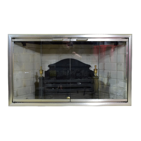
WARNING: ALWAYS LEAVE GLASS DOORS
FULLY OPENED OR FULLY CLOSED WHEN
OPERATING THIS FIREPLACE.
DESA INTERNATIONAL
2701 INDUSTRIAL DRIVE
P.O. BOX 90024
BOWLING GREEN, KY 42102-9004
www.desatech.com
Models
: 36E Non-Circulating (Smooth Face)
I36E Non-Circulating (Smooth Face) Fully Insulated
SAVE THIS BOOK
This Fireplace is approved for use as a Wood Burning Fireplace or for
use with a vented gas log approved to ANS Z21.60, Z21.84 or RGA 2-
72 Standards or for use with a vent-free gas log heater approved to
ANS Z21.11.2 standard. A DESA hood must be installed when using a
vent-free gas log set (See accessories on pg. 11).
ELIMINATOR
36" Wood Burning Fireplace
ICBO ES ER-3507
PN 54013
REV B
10/00
Advertisement
Table of Contents

Related Manuals for FMI ELIMINATOR 36E


Summary of Contents for FMI ELIMINATOR 36E
- Page 1 ELIMINATOR 36” Wood Burning Fireplace Models : 36E Non-Circulating (Smooth Face) I36E Non-Circulating (Smooth Face) Fully Insulated INSTALLATION INSTRUCTIONS SAVE THIS BOOK This book is valuable. In addition to instructing you on how to install your fireplace, it also contains information that will enable you to obtain replacement parts or optional accessory items when needed.
-
Page 2: Table Of Contents
CONTENTS SAFETY INFORMATION --------------------------------------------------------------------------------- PG. 2 GLOSSARY --------------------------------------------------------------------------------- PG. 2 3. INTRODUCTION --------------------------------------------------------------------------------- PG. 2 4. BEFORE YOU BEGIN --------------------------------------------------------------------------------- PG. 2 5. SELECTING LOCATION --------------------------------------------------------------------------------- PG. 2 6. MINIMUM CLEARANCES TO COMBUSTIBLE ---------------------------------------------------------------------------- PG. 3 7. INSTALLING THE FIREPLACE --------------------------------------------------------------------------------- PG. -
Page 3: Safety Information
WARNING: SAFETY INFORMATION g) Outside Air Kit – a combustion air inlet that allows combustion air to enter the firebox area through a duct. • Do not store or use gasoline or any other flammable vapors or liquids in the vicinity of this or any other appliance. -
Page 4: Minimum Clearances To Combustible
extend under the fireplace a minimum of 1”. The ember protector should be made of galvanized sheet metal (28 Ga. minimum) to prevent corrosion (see figure 5). STEP 6: Secure the fireplace to the framing through flanges located on the sides of the fireplace (see figure 4). Figure 1 TYPICAL FIREPLACE LOCATIONS MINIMUM CLEARANCES TO COMBUSTIBLES: Figure 2... -
Page 5: Hearth Extension
HEARTH EXTENSION: A hearth extension is required to protect the combustible floor constructed in front of the fireplace. The hearth extension is not included and must be fabricated. The hearth extension must project at least 12 inches beyond each side of the fireplace opening (see drawing on front cover). -
Page 6: Vent Free Gas Log Installation
A gas line may be installed for the purpose of installing a line if desired. Follow the manufacturer’s installation vented or vent-free gas appliance available through your local instructions provided with the gas appliance. distributor. Use a ½” black iron pipe and appropriate fittings. CAUTION: All gas piping and connections must be When installing a gas line, a shut-off valve designed for tested for leaks after the installation is completed. -
Page 7: Chimney Pipe
5. Do not insulate on top of the firebox. The opening in the recommended height would be preferable to provide a better collar around the chimney at the top of the fireplace must not draw. be obstructed (see figure 11). Maximum height approved for any chimney run with this fireplace system is 40 feet as measured from the bottom of the fireplace to the flue outlet-end of the termination. - Page 8 1 elbow set – 14 to 40 ft. system height, 2 elbow sets – 22 to 40 ft. system height. Figure 13 TYPICAL OFFSET INSTALLATIONS INSTRUCTIONS WHEN OFFSET OF CHIMNEY IS NEEDED Installing offset and return elbow (30E-8DM) 1. To achieve desired offset, you may install combination of 12”, 18”, 24”, 36”...
-
Page 9: Penetrating The Roof
PENETRATING THE ROOF: To maintain a 1-inch clearance to the pipe on the roof with a pitch, a rectangular opening must be cut. STEP 1: Determine the center point through which the pipe will penetrate the roof. Figure 16 FIRESTOP INSTALLATION STEP 2: Determine the pitch of the roof. -
Page 10: Flashing Installation
FLASHING INSTALLATION: FOLLOW INSTALLATION INSTRUCTIONS (V6F-8DM or V6F-8DM) PROVIDED WITH THE TERMINATION BEING USED. Determine the flashing to be used with the roof-opening chart. Slide flashing over pipe until base is flat against roof. Replace as many shingles as needed to cover exposed area and flashing base. -
Page 11: Finishing The Fireplace
Mantels or any other combustible material may butt up to the side of the black metal face of the fireplace. The clearances from the side of the fireplace to any combustible material and wall should fall within the limits shown in figure 26. Figure 24 10 FOOT RULE FINISHING THE FIREPLACE:... -
Page 12: Replacement And Accessory Parts
REPLACEMENT PARTS (CONTACT YOUR LOCAL DEALER) ACCESSORY PARTS (CONTACT YOUR LOCAL DEALER) Desa International 2701 Industrial Drive, P.O. Box 90024, Bowling Green, KY 42102-9004 www.desatech.com, (800) 323-5190 For more information, visit www.desatech.com...
Need help?
Do you have a question about the ELIMINATOR 36E and is the answer not in the manual?
Questions and answers