Advertisement
Quick Links
SERVICE MANUAL
11
2004
YF058
1
PRECAUTIONS . . . . . . . . . . . . . . . . . . . . . . . . . . . . . . . . . . . . . . . . . . . . . . . . . . . . . . . . . . . . . . . . . . . . . . . 1-3
2
SPECIFIC SERVICE INSTRUCTIONS . . . . . . . . . . . . . . . . . . . . . . . . . . . . . . . . . . . . . . . . . . . . . . . . . . . . . . 1-5
3
DISASSEMBLY . . . . . . . . . . . . . . . . . . . . . . . . . . . . . . . . . . . . . . . . . . . . . . . . . . . . . . . . . . . . . . . . . . . . . . 1-21
4
ADJUSTMENT . . . . . . . . . . . . . . . . . . . . . . . . . . . . . . . . . . . . . . . . . . . . . . . . . . . . . . . . . . . . . . . . . . . . . . . 1-28
5
TROUBLE SHOOTING . . . . . . . . . . . . . . . . . . . . . . . . . . . . . . . . . . . . . . . . . . . . . . . . . . . . . . . . . . . . . . . . . 1-30
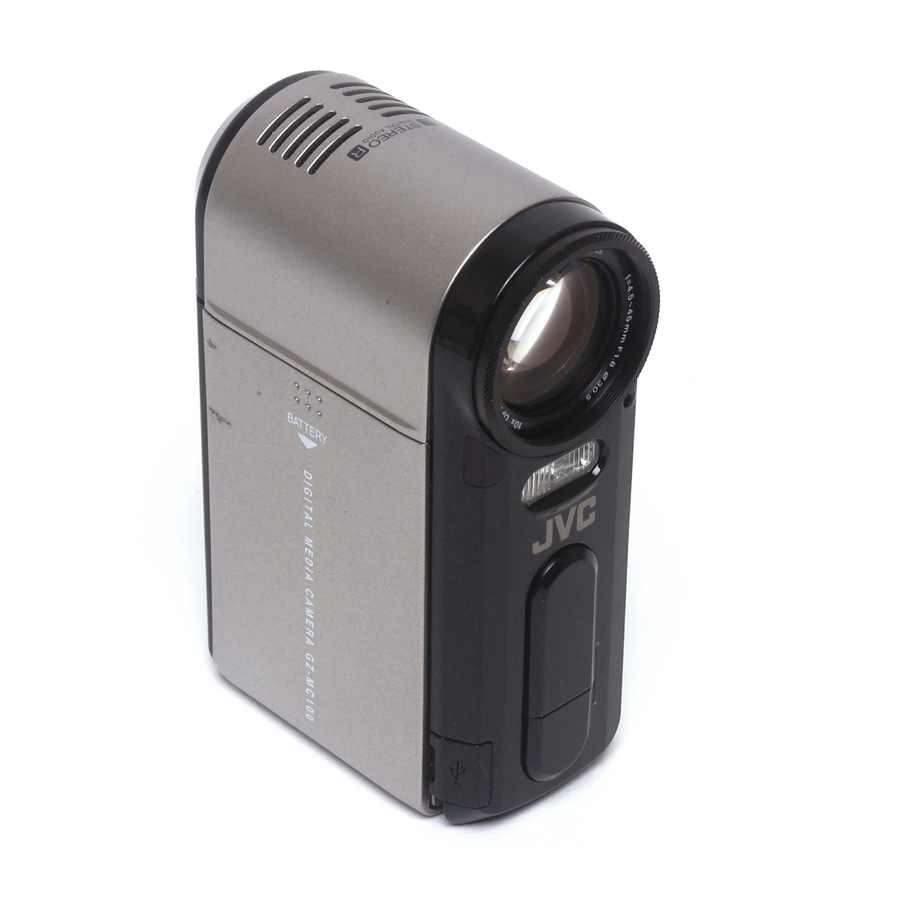
DIGITAL MEDIA CAMERA
GZ-MC100US
TABLE OF CONTENTS
COPYRIGHT © 2004 Victor Company of Japan, Limited
GZ-MC100US [M4S327]
No.YF058
2004/11
Advertisement

Related Manuals for JVC GZ-MC100US


Summary of Contents for JVC GZ-MC100US
-
Page 1: Table Of Contents
2004 GZ-MC100US GZ-MC100US [M4S327] TABLE OF CONTENTS PRECAUTIONS ............... 1-3 SPECIFIC SERVICE INSTRUCTIONS . - Page 2 SPECIFICATION 1-2 (No.YF058)
-
Page 3: Precautions
SECTION 1 PRECAUTIONS SAFTY PRECAUTIONS Prior to shipment from the factory, JVC products are strictly emission. Consequently, when servicing these products, inspected to conform with the recognized product safety and replace the cathode ray tubes and other parts with only the electrical codes of the countries in which they are to be specified parts. - Page 4 1.1.2 Safety Check after Servicing Examine the area surrounding the repaired location for damage (4) Leakage current test or deterioration. Observe that screws, parts and wires have been Confirm specified or lower leakage current between earth returned to original positions, Afterwards, perform the following ground/power cord plug prongs and externally exposed tests and confirm the specified values in order to verify accessible parts (RF terminals, antenna terminals, video...
-
Page 5: Specific Service Instructions
SECTION 2 SPECIFIC SERVICE INSTRUCTIONS Handling Microdrives Microdrives are used in GZ-MC100 and GZ-MC200. Although the appearance is different, a Microdrive is exactly the same as a hard disc that is used in a PC. Therefore, unlike handling conventional tapes, caution must be paid in handling Microdrives. The handling of Microdrives is explained in this section. - Page 6 2.1.2 Precautions on handling Microdrives NOTE: Main causes of failures in hard disks including Microdrives are The shock of 200G(G:Gravity), a maximum impact value in listed as follows. operation, is equivalent of the impact of dropping from 20- (1) Failures caused by shocks 30cm above the hard floor.
- Page 7 2.1.3 Microdrive backup 2.1.4.1 Separations of the parts failures Unlike the information on tapes, customers' information on The procedure to identify the causes of the failures whether it is Microdrives can become unreadable in an instant. Backing up in the main unit or in the Microdrive is explained in this section. users' record is strongly recommended to avoid any accident.
- Page 8 When it is submerged, the white 2.1.4.4 Water Exposure Seal turns to red. As the center part of the seal turns to pink, the color seen from the hole is pink. The 1mm hole Normal condition Main unit diameter prevents the seal from diagnosis getting affected by wet hands Perform an operation check with CF and SD.
- Page 9 Recovery method There are levels in erasing data in disks. Asking a data recovery company (a data salvage company) • Level 1: Zero Write method (once) seems the only way. • Level 2: Random Write method (once) Even if the MD is not recognized a drive, a transmission may be •...
- Page 10 2.1.5.2.2 Recording time (approximately minutes) Ultra fine Fine Normal Economy On the package of the product, 720 480 720 480 720 480 352 240 it is noted as high-speed type. SD CF 128MB 2 minutes 3 minutes 10 minutes 4 minutes SD CF 256MB 4 minutes 6 minutes...
- Page 11 The handling of this software is explained as follows. Notice This software is developed to confirm, analyze, and restore the various kinds of hard disks. However, JVC is allowed to use DDD software only to test, confirm, and restore the Microdrive to the factory setting.
- Page 12 JVC etc. NOTE: Although Registration Info requires ID registration, there is no need to register, as it has nothing to do with JVC- VICTOR. (6) Press Next button, to continue the installation. Next button is displayed after some letters are input in the Company box.
- Page 13 Click the Resources tab (2) From the DDD SETUP folder, copy the shortcut icons (2 kinds) shown below to the desktop. (These are the links for the program exclusive to JVC.) NOTE: The names of icons, display contents and display parts differ according to the types of installed OS, their ver- sions, and each PC's settings.
- Page 14 (7) Take notes of the I/O range, then press Cancel button to (10) Select all the files in the input folder and delete them all. close the Property Setting window. Select all the files the folder and delete Take notes of the I/O range shown here NOTE: These files are used for other hard disks.
- Page 15 Executing DDD may destroy all the user information, and re- covery may become impossible. In DDD there are two definition files (pid files) that have the information which determines the operation of DDD. Two pid files are exclusively prepared for JVC. They are: FullCheckMicrodrive_jvc.pid, CleanDisk.pif 2.1.6.6.1 FullCheckMicrodrive_jvc.pid (FullCheck) FullCheckMicrodrive_jvc.pid is the confirmation pid file to confirm...
- Page 16 (5) Press the Media Recognition button (shown above) to rec- NOTE: ognize the medium. Although the usual checking time is about 15-20 min- utes, it varies depending on the each PC's performance. If it takes too long (more than 30 minutes), there may be Click to take off the check a failure in checking.
- Page 17 (13) When " Are you sure you want to end the application?" is drive, model name of the drive and the production place are displayed, press Yes (Y) to finish the application. also written. Drive model name Production place Press Yes (Y) button 2.1.6.6.2 Test results and countermeasure 1.2.6.6.1Reviewing the test results of FullCheckMicrodrive_jvc.
- Page 18 THIS DRIVE TO YOUR SUPPLIER" is displayed. In the early stage, the defected parts are analyzed for modification. Please follow the instruction from JVC. 7. The time and date of the start and end the testing are dis- played here.
- Page 19 NOTE: Although the usual checking time is about 15 - 30 min- utes. If it takes too long (more than 45 minutes), there Press X button may be a failure in checking. Finish the checking by pressing Abort button and start the checking again. (10) Press either the Print button or the View button to print or display the test results.
- Page 20 WIRING DIAGRAM 1-20 (No.YF058)
-
Page 21: Disassembly
SECTION 3 DISASSEMBLY BEFORE ASSEMBLY AND DISASSEMBLY • 3.1.1 Precautions Torque driver • Be sure to disconnect the power supply unit prior to mounting Be sure to use to fastening the mechanism and exterior parts and soldering of parts. because those parts must strictly be controlled for tightening •... - Page 22 3.2.2 ASSEMBLY/DISASSEMBLY OF CABINET PARTS AND ELECTRICAL PARTS Disassembly procedure STEP Fig. PART NAME POINT NOTE COVER(SPK) ASSY 2(S1) COVER(REAR) 5(S2) OPERATION UNIT 2(S3),CN3 NOTE3a,b COVER(BATT.) LOWER CASE ASSY SHEET(BOTTM),6(S5),CN5 NOTE5a,b TOP COVER ASSY S6,CN6 NOTE6a,b FRONT COVER ASSY S7a,(S7b),CN7 DIGITAL BOARD ASSY SPACER,CN8a,b,c,d,e,S8, CN8f,g NOTE8...
- Page 23 (S7a) (S5) (S5) NOTE5b COVER(USB) (S5) (S5) (S5) (S5) (S7b) (S7b) SHEET(BOTTOM) NOTE5a 0.069N m (0.7kgf cm) Fig.FA3 Fig.FA5 SPACER CN8d CN8c CN8b (S8) CN8a CN8f CN8e (S6) NOTE8 CN8g WIRE NOTE6a NOTE6b Fig.FA4 Fig.FA6 (No.YF058)1-23...
- Page 24 [11] (S9) (S9) (S11) L11a L11b (S11) L11c Fig.FA7 Fig.FA9 <NOTE10a,b> [12] [10] CATCH NOTE10a SLIDER [10] [13] SPRING MONITOR ASSY NOTE10b CATCH NOTE12 L12a (S10) L12b (S10) (S12) (S12) (S12) 0.098N m (1.0kgf cm) Fig.FA8 Fig.FA10 1-24 (No.YF058)
- Page 25 3.2.3 DISASSEMBLY of [13] MONITOR ASSEMBLY CAUTIONS (2) Remove the CONNECTOR CN13a. (1) Remove the MONITOR ASSEMBLY from the UPPER (3) Peel off the SPACERS, and remove the BRACKETS CASE ASSEMBLY first, as they are removed together in (MONI.PWB). main parts disassembly, and then proceed to the disas- (4) Remove the CONNECTOR CN13b, and remove the sembly procedure.
- Page 26 3.2.4 DISASSEMBLY of [12] OP BLOCK ASSY/CCD BOARD ASSY CAUTIONS Replacing service repair parts (1) Since the OP BLOCK on this model is more complicated The service repair parts of the OP BLOCK ASSEMBLY are as in structure than previous OP BLOCKS, pay extra follows.
- Page 27 (S12e) (S12d) (S12d) SD12b SENSOR (S12c) IRIS MOTOR UNIT NOTE12e,f (S12c) FOCUS MOTOR NOTE12c,d ZOOM MOTOR NOTE12c,d (S12c) (S12c) OP BLOCK : 0.078N m (0.8kgf cm) : 0.088N m (0.9kgf cm) Fig.3-2-4-2 (No.YF058)1-27...
-
Page 28: Adjustment
SECTION 4 ADJUSTMENT PREPARATION 4.1.3 TOOLS REQUIRED FOR ADJUSTMENT 4.1.1 Precaution Torque Driver Tweezers YTU94088 YTU94088-003 P-895 Camera system and deck system of this model are specially adjusted by using PC. However, if parts such as the following are replaced, an adjustment is required. - Page 29 • INF adjustment lens JIG CONNECTOR CABLE CONNECTION To be used for adjustment of the camera system. For the Connection procedure usage of the INF adjustment lens, refer to the Service Bulletin No. YA-SB-10035. • INF lens holder To be used together with the Camera stand for operating the Videocamera in the stripped-down condition such as the sta- JIG CONNECTOR tus without the exterior parts or for using commodities that are...
-
Page 30: Trouble Shooting
SECTION 5 TROUBLE SHOOTING SERVICE NOTE 1-30 (No.YF058) - Page 31 Victor Company of Japan, Limited AV & MULTIMEDIA COMPANY CAMCORDER CATEGORY 12, 3-chome, Moriya-cho, kanagawa-ku, Yokohama, kanagawa-prefecture, 221-8528, Japan (No.YF058) Printed in Japan...
Need help?
Do you have a question about the GZ-MC100US and is the answer not in the manual?
Questions and answers