Table of Contents
Advertisement
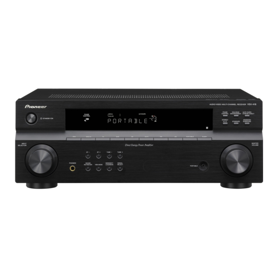
AUDIO/VIDEO MULTI-CHANNEL RECEIVER
VSX-418-K
VSX-418-S
THIS MANUAL IS APPLICABLE TO THE FOLLOWING MODEL(S) AND TYPE(S).
Model
Type
VSX-418-K
MYSXJ5
VSX-418-S
MYSXJ5
For details, refer to "Important Check Points for good servicing".
PIONEER CORPORATION
PIONEER ELECTRONICS (USA) INC. P.O. Box 1760, Long Beach, CA 90801-1760, U.S.A.
PIONEER EUROPE NV Haven 1087, Keetberglaan 1, 9120 Melsele, Belgium
PIONEER ELECTRONICS ASIACENTRE PTE. LTD. 253 Alexandra Road, #04-01, Singapore 159936
PIONEER CORPORATION
STANDBY / ON
INPUT
SELECTOR
Power Requirement
AC 220 V to 230 V
AC 220 V to 230 V
4-1, Meguro 1-chome, Meguro-ku, Tokyo 153-8654, Japan
2008
VSX-418
AUDIO/VIDEO MULTI-CHANNEL RECEIVER
PHASE
DIALOGUE
AUTO SURR /
CONTROL
ENHANCEMENT
STREAM DIRECT
PHASE
CONTROL
STEREO /
ADVANCED
A.L.C.
STANDARD
SURROUND
DVD
DVD 5.1
TV
DVR
CD
CD-R
FM
AM
PORTABLE
SLEEP
PHONES
SOUND
MIDNIGHT/
SIGNAL
RETRIEVER
VSB MODE
LOUDNESS
SELECT
PORTABLE
VSX-418-K
MASTER
VOLUME
ORDER NO.
RRV3737
Remarks
2008 Printed in Japan
T-ZZK MAR.
Advertisement
Table of Contents


Need help?
Do you have a question about the VSX-418-K and is the answer not in the manual?
Questions and answers