Table of Contents
Advertisement
Quick Links
dummyhead
dummyhead
How to use this manual
INTRODUCTION
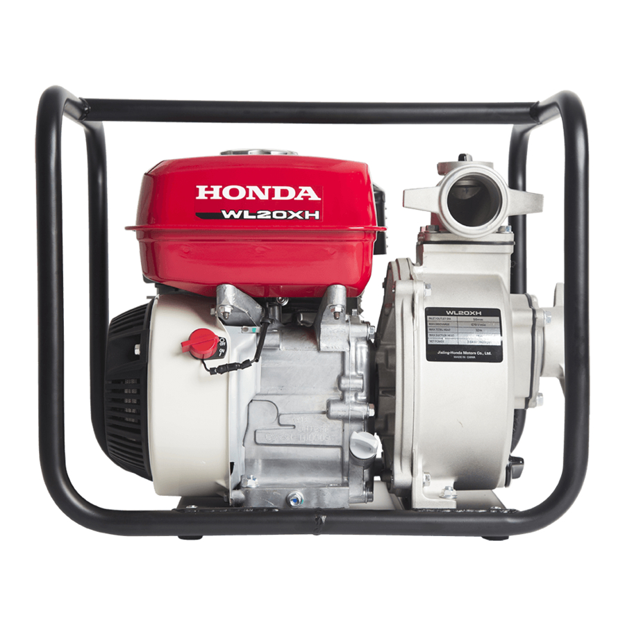
This supplement covers the construction, function, and
servicing procedures of the Honda WL20XH BRX type
water pump.
For service information that is not covered in this
supplement, please refer to the WL20/WL30 base shop
manual (part number 82YG800).
All information contained in this manual is based on the
latest product information available at the time of
printing. We reserve the right to make changes at
anytime without notice.
No part of this publication may be reproduced, stored in
a retrieval system, or transmitted, in any form, by any
means, electronic, mechanical, photocopying,
recording, or otherwise, without prior written permission
of the publisher. This includes text, figures, and tables.
As you read this manual, you will find information that is
preceded by a
symbol. The purpose of this
message is to help prevent damage to this Honda
product, other property, or the environment.
SAFETY MESSAGES
Your safety and the safety of others are very important.
To help you make informed decisions, we have
provided safety messages and other safety information
throughout this manual. Of course, it is not practical or
possible to warn you about all the hazards associated
with servicing these products. You must use your own
good judgement.
You will find important safety information in a variety of
forms, including:
· Safety Labels – on the product.
· Safety Messages – preceded by a safety alert symbol
and one of three signal words, DANGER,
WARNING, or CAUTION.
These signal words mean:
You WILL be KILLED or SERIOUSLY
HURT if you don't follow instructions.
You CAN be KILLED or SERIOUSLY
HURT if you don't follow instructions.
You CAN be HURT if you don't follow
instructions.
· Instructions – how to service these products correctly
and safely.
© Honda Motor Co., Ltd.
SERVICE PUBLICATION OFFICE
Date of Issue: September 2014
How to use this manual
OUTLINE OF CHANGES
SPECIFICATIONS
SERVICE INFORMATION
MAINTENANCE
TROUBLESHOOTING
COVER
FUEL SYSTEM
GOVERNOR SYSTEM
IGNITION SYSTEM
STARTING SYSTEM
PUMP
ENGINE REMOVAL/INSTALLATION
CYLINDER HEAD
CRANKCASE
MUFFLER
WIRING DIAGRAMS
INDEX
The marked sections contain no changes.
They are not covered in this supplement.
1
2
3
4
5
6
7
8
9
10
11
12
13
14
15
0-2
Advertisement
Table of Contents

Related Manuals for Honda WL20XH


Summary of Contents for Honda WL20XH
- Page 1 INTRODUCTION OUTLINE OF CHANGES This supplement covers the construction, function, and SPECIFICATIONS servicing procedures of the Honda WL20XH BRX type water pump. SERVICE INFORMATION For service information that is not covered in this supplement, please refer to the WL20/WL30 base shop MAINTENANCE manual (part number 82YG800).
- Page 2 dummyhead dummyhead How to use this manual SYMBOLS The symbols used throughout this manual show specific service procedures. If supplementary information is required pertaining to these symbols, it will be explained specifically in the text without the use of the symbols. Replace the part(s) with new one(s) before assembly.
-
Page 3: Outline Of Changes
dummyhead dummyhead OUTLINE OF CHANGES How to use this manual ITEM After modification Before modification Air cleaner DUAL TYPE SEMI DRY TYPE... - Page 4 dummyhead dummyhead MEMO...
-
Page 5: Specifications
dummytext 1. SPECIFICATIONS SPECIFICATIONS·································· 1-2... -
Page 6: Dimensions And Weights
SPECIFICATIONS SPECIFICATIONS SPECIFICATIONS DIMENSIONS AND WEIGHTS Model WL20XH Description code WADC Type Overall length 490 mm (19.3 in) Overall width 385 mm (15.2 in) Overall height 410 mm (16.1 in) Dry weight 24 kg (53 lbs) Operating weight... -
Page 7: Service Information
dummytext 2. SERVICE INFORMATION MAINTENANCE STANDARDS ················· 2-2... -
Page 8: Maintenance Standards
dummyhead dummyhead SERVICE INFORMATION MAINTENANCE STANDARDS SERVICE INFORMATION Unit: mm (in) Part Item Standard Service limit Carburetor Main jet BEA2M A – Pilot screw opening 2-1/2 turns out – Float height 13.7 (0.54) –... -
Page 9: Maintenance
dummytext 3. MAINTENANCE AIR CLEANER CHECK/CLEANING/REPLACEMENT ········ 3-2... - Page 10 dummyhead dummyhead MAINTENANCE AIR CLEANER MAINTENANCE CHECK/CLEANING/REPLACEMENT A dirty air filter will restrict air flow to the carburetor, reducing engine performance. If the engine is operated in dusty areas, clean the air cleaner more often than specified in the MAINTENANCE SCHEDULE. Operating the engine without the air filters or with the filter installed loosely will allow dirt to enter the engine, causing rapid engine wear.
- Page 11 dummyhead dummyhead MAINTENANCE CLEANING FOAM Clean the filter [1] in warm soapy water, rinse, and allow to dry thoroughly, or clean with a non-flammable Squeeze solvent and allow to dry thoroughly. and dry Dip the filter in clean engine oil, and squeeze out all the excess oil.
- Page 12 dummyhead dummyhead MEMO...
-
Page 13: Fuel System
dummytext 6. FUEL SYSTEM AIR CLEANER REMOVAL/INSTALLATION ····················· 6-2... - Page 14 dummyhead dummyhead FUEL SYSTEM AIR CLEANER FUEL SYSTEM REMOVAL/INSTALLATION WING NUT AIR CLEANER COVER WING NUT GROMMET INNER FILTER (PAPER) OUTER FILTER (FOAM) BOLT (6 x 20 mm) AIR CLEANER ELBOW SEAL COLLAR AIR CLEANER ELBOW REMOVAL/INSTALLATION: Remove and install the air cleaner elbow with the fuel valve lever in the OFF position and the choke lever...
- Page 15 INDEX dummytext INDEX AIR CLEANER CHECK/CLEANING/REPLACEMENT···3-2 MAINTENANCE STANDARDS ································2-2 AIR CLEANER REMOVAL/INSTALLATION ················6-2 SPECIFICATIONS·················································1-2...
Need help?
Do you have a question about the WL20XH and is the answer not in the manual?
Questions and answers