Table of Contents
Advertisement
Quick Links
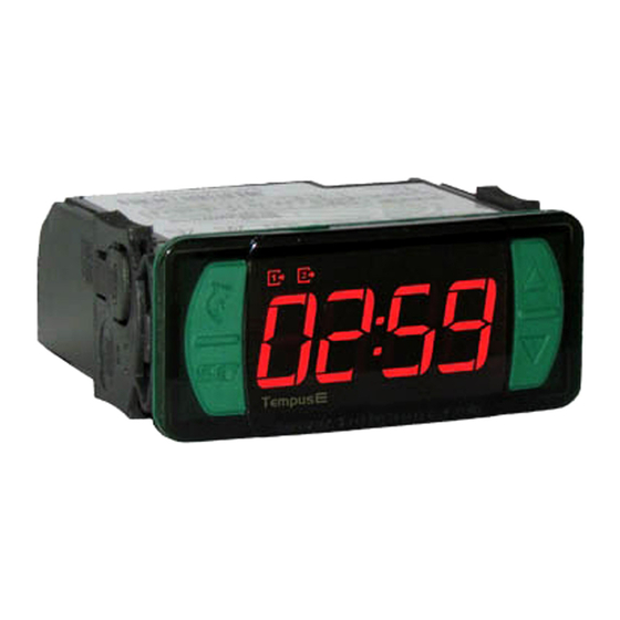
1. DESCRIPTION
A digital timer/counter with programmable time base that operates in both cyclical functions as well as in
functions that are triggered by a key/switch. It has an internal audible alarm (buzzer) and an output to
activate the process finish alarm and event totalizer. The Tempus
presets for the timer and counter modes, in addition to the configuration of a delay between timer cycles
where two outputs remain off. It also features a digital input to start the cyclical timer, different time units
for on and off times in the cyclical timer mode, event accumulator for the timer/counter modes, and
Counter Mode for low frequency counting with dry contact.
Product conforming to UL Inc. (United States and Canada).
2. SAFETY RECOMMENDATIONS
- Check the controller for correct fastening;
- Make sure that the power supply is off and that it is not turned on during the controller installation;
- Read the present manual before installing and using the controller;
- Use adequate Personal Protective Equipmenet (PPE);
- For application at sites subject to water spills, install the protecting vinyl supplied with the controller;
- The installation procedures should be performed by a qualified technician.
3. APPLICATIONS
• Ovens, injection machines, defrost control
• Process monitoring and control.
• Rewinders
• Packing machines
• Electric panels in general
4. TECHNICAL SPECIFICATIONS
Electric supply
Operating temperature
Maximum current per output
Precision (timer/cyclical timer)
Maximum frequency (counter)
Counter input
Operating humidity
Dimensions (mm)
Dimensions for cutting - to fasten
the instrument
(*)
Acceptable variation in relation to the rated voltage.
5. INDICATORS AND KEYS
Indication of OUT2 output activated
Indication of OUT1 output activated
Quick Access
Menu Key (Flatec)
Set key
e
Tempus
6. WIRING DIAGRAM
6.1. Identifications (see Images I and II)
- Image I: TempusE, supplied at 115 Vac.
- Image II: TempusE, supplied at 230 Vac.
Image I: TempusE - 115Vac
WIRING
NC
TERMINALS
OUT2
115 Vac
OUT1
Tempus
DIGITAL TIMER
Serial
Buzzer
programming
e
allows you to set up to three
TempusE: 115 or 230 Vac ±10%(*)(50/60 Hz)
0 to 50 ºC / 32 to 122°F
OUT1: 16(12)A 250Vac 1HP
OUT2: 10A / 250Vac ¼ HP
0,05% FE
100cps - counts per second (100 Hz)
NO/NC (dry contact) No - voltage input
10 to 90% RH (no condensation)
76 x 34 x 77 mm (WxHxD)
71 ± 0,5 x 29 ± 0,5 mm (see image V)
CONTROLLER
Image II: TempusE - 230 Vac
WIRING
TERMINALS
WIRING
TERMINALS
OUT2
}
POWER
GRID
e
IP 65
FRONT
Degree
of protection
6.2. Controller power supply
Use the pins according to table below, considering the set version:
6.3. Recommendations of IEC60364 standard
a) Install overload protectors in the controller supply.
b) Install transient suppressors - suppressor filter RC - in the circuit to increase the service life of the
controller relay. See connection instructions of the filter on the previous page.
7. FASTENING PROCEDURE
a) Cut out the panel plate (Image V - item 14) where the controller shall be fastened, with sizes
X = 71±0.5 mm and Y = 29±0.5 mm;
b) Remove side locks (Image VI - item 14): to do that, compress the central elliptical part (with the Full
Gauge Controls logo) and displace the locks backwards;
c) Introduce the controller in the notch made on the panel, inwards;
d) Place the locks again and then displace them until they compress into the panel, fastening the
controller to the housing (see arrow indication in Image VI - item 14);
e) Perform the electric installation as described in item 6;
f) Adjust the parameters as described in item 10.
ATTENTION: for installations requiring liquid tight sealing, the notch sizes for the controller
installation should be no more than 70.5x29mm. The side locks should be fastened so that they
press the sealing rubber avoiding infiltration between the notch and the controller.
Protector vinyl - Image VII (item 14)
It protects the controller when installed at a site subject to water spills, such as refrigerated counters.
This adhesive vinyl is supplied with the instrument in the package.
IMPORTANT: Make the application only after completing the electrical connections.
a) Retreat the side locks (Image VI - item 14);
b) Remove the protective film from the adhesive vinyl face;
c) Apply the vinyl over the entire upper part, bending the flaps, as indicated by the arrows - Image VII
(item 14);
d) Reinstall the locks.
NOTE: The vinyl is transparent, allowing visualization of the wiring system of the instrument
Upper Key
Lower Key
CONTROLLER
NC
OUT2
230 Vac
OUT1
OUT2
T em pu se
T em pu se
Pins
9 and 10
9 and 11
IMPORTANT
INSTRUMENTS IN THE EVOLUTION SERIES HAVE TWO
DIFFERENT TERMINAL SIZES, BUT BOTH ARE COMPATIBLE
WITH THE SCREWDRIVER 2.0MM. USING THE APPROPRIATE
TOOLS DURING INSTALLATION ENSURES A LONGER LIFE AND
THE PROPER OPERATION OF THE PRODUCTS.
WIRING
TERMINALS
Surge Protective Device (SPD)
(sold separately)
W i r i n g d i a g r a m f o r
instalation of SPD in
magnectic contactor
A1 and A2 are the terminals
of the contactor coil.
A1
}
POWER
A2
GRID
evolution
E251415
TEMPUS E
115 Vac
230 Vac
W i r i n g d i a g r a m f o r
instalation of SPD in line
with loads
For direct drive take in to
consideration the specified
maximum current.
Load
Advertisement
Table of Contents

Subscribe to Our Youtube Channel
Related Manuals for Full Gauge Controls Tempus E


Summary of Contents for Full Gauge Controls Tempus E
- Page 1 It has an internal audible alarm (buzzer) and an output to activate the process finish alarm and event totalizer. The Tempus Pins TEMPUS E allows you to set up to three 9 and 10...
- Page 2 10.2 Access code [Code] 8. OPERATIONS To allow the altering of parameters, enter the option [Code] by pressing (quick touch), enter the 8.1. Quick Access Menu Map < > access code 123 (one hundred and twenty-three) using the keys, and confirm with Use the key (Flatec) to access or browse the quick access menu.
- Page 3 [Uni2] - Units of the preset's time base[RC2,]: 10.5.2 Setup [Sec,]- Seconds and hundredths. With the cyclical timer selected, the following configurations are available. [Min,]- Minutes and seconds. [Hour]- Hours and minutes. [Uton] - ON time base units: Establishes the time base for which the cyclical timer will remain on (On time). [tRC2] - Timing of preset[RC2,]: [Sec,]- Seconds and hundredths.
- Page 4 This parameter allows changing the desired value for the preset’s counting. This parameter can also be [eCAL] Contact Full Gauge Controls. changed in the quick access menu (see item 8.1). NOTE: The following parameters: [Fcnt], [disp], [tpul], [talr] ,[buss]and [rest] are [pppp] Reconfigure the values of the functions.
- Page 5 If in doubt, please contact Full Gauge Controls. Products manufactured by Full Gauge Controls, as of May 2005, have a two (02) year warranty, as of the date of the consigned sale, as stated on the invoice. They are...
Need help?
Do you have a question about the Tempus E and is the answer not in the manual?
Questions and answers