Table of Contents
Advertisement
Quick Links
Advertisement
Table of Contents

Related Manuals for Crestron CNMSX-PRO


Summary of Contents for Crestron CNMSX-PRO
-
Page 3: Table Of Contents
Rack Mounting ... 11 Bussing Strip Installation ... 12 Network Wiring... 12 Hardware Hookup ... 14 Programming the LCD Display (available on CNMSX-PRO only)... 15 Front Panel Editor ... 15 Creating a Page with Front Panel Editor ... 16 Object Types ... 18 Loading Crestron Control Software... -
Page 5: Integrated Control System: Cnmsx
There are two CNMSX configurations available: the PRO and AV. The PRO is the flagship product in Crestron’s new generation of control systems. It is the model that has all the features mentioned in the previous section. The AV is a cost-competitive alternative to the PRO. -
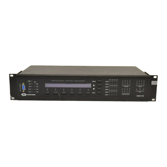
Page 6: Physical Description
AV configuration. buttons, and an extended bank of LED indicators*. The front panel of the CNSMX- PRO and AV are shown below. CNMSX-PRO Front Panel CNMSX-AV Front Panel An asterisk (*) indicates that Located on the rear panel, shown on the next page for each configuration, there are... - Page 7 CRESNET 4-Wire and 6-Pin Connectors On the rear panel there are two network connectors: 4-wire and modular. The 4-pin male connector (typical Crestron network port labeled 24 Y Z G) and 6-wire RJ-type connector are used for expansion to Cresnet and SmarTouch peripherals. Depending on the expansion slot load, there is a 50 W maximum load rating.
- Page 8 NOTE: The pinout of each 9-pin port is non-standard (refer to table after this note, titled “Non-Standard COM Pinout” ); it contains RS-422 pins in addition to RS-232. 4 • Integrated Control System: CNMSX Crestron CNMSX Operations Guide - DOC. 8118B...
- Page 9 Crestron CNMSX This may result in a conflict with some equipment and therefore do not use all nine pins. Only the required pins for each communication type should be connected. NOTE: To support RS-485, tie pin 1 (RXD-) to pin 9 (TXD-) and pin 4 (TXD+) to pin 6 (RXD+) in the cable (refer to table after this note, titled “COM Pinout to RS-...
- Page 10 LED is also high. When RTS flow control is enabled, RTS indicates the unit is ready to receive data from serial devices attached to respective COM ports. 6 • Integrated Control System: CNMSX Crestron CNMSX Operations Guide - DOC. 8118B...
- Page 11 5 of "Troubleshooting Communications" on page 26) performs an overload/reset. CNMSX LCD Display The front panel of the CNMSX-PRO incorporates a reverse mode (yellow on black) LCD display, shown below. The screen contains two lines with 40 characters per line;...
- Page 12 The menu contents are subject to programming and an example of this display is provided in "Programming the LCD Display (available on CNMSX-PRO only)" on page 15. INFO This button displays a default Info Menu, shown below. System information,...
-
Page 13: Leading Specifications
FTP site. Filenames for CNX upgrades have a UPZ extension and can be obtained from the Downloads page (OPSYS Library) of the Crestron website. For a CNMSX with e-control™ use the latest UPZ upgrade file from the ECONTROL Library. - Page 14 Direct Processor Access expansion slot for optional local area network (LAN) interface card; CNXENET+ requires field installation and has (1) 8-wire RJ45 connector for communication acces CNXCAGE, 3-card cage, installation required for CNMSX-AV. Crestron CNMSX DETAILS DETAILS DETAILS Operations Guide - DOC. 8118B...
-
Page 15: Setup
Crestron CNMSX As of the date of manufacture, the unit has been tested and found to comply with specifications for CE marking. NOTE: This device complies with part 15 of the FCC rules. Operation is subject to the following two conditions: (1) this device may not cause harmful interference, and (2) this device must accept any interference received, including interference that may cause undesired operation. -
Page 16: Bussing Strip Installation
12 • Integrated Control System: CNMSX FASTEN WITH THE SAME (3) COVER SCREWS LEFT SIDE VIEW OF CNMSX-PRO/AV WITH OPTIONAL RACK MOUNTING EARS INSTALLED 4. Repeat procedure (steps 1 through 3) to attach remaining ear to opposite side. - Page 17 RECOMMENDED COLOR CODE Modular Network Connector For modular cable connections in a Crestron remote control system, the six-conductor modular cable is used to power Crestron devices. That cable must be rated for 30 Operations Guide - DOC. 8118B 40,000 Where: R = Resistance (refer to table below).
-
Page 18: Hardware Hookup
Refer to the hookup diagram on the next page and aside from attaching power last, complete the connections in any order. NOTE: Refer to the latest revision of the Crestron Network Modular Cable Requirements (Doc. 5682) or Network Interconnect Drawing (Doc. 5411) when making connections to the port labeled CRESNET. -
Page 19: Programming The Lcd Display (Available On Cnmsx-Pro Only)
PANEL (left-most, function) button on the LCD display. Front Panel Editor The LCD display on a CNMSX-PRO has different pages that are defined by the programmer. Menu function buttons are assigned to different pages or objects. The LCD display has a 2x40 character display with six-programmable buttons. -
Page 20: Creating A Page With Front Panel Editor
“Edit Panel Object” dialog box appears. From the Menu Jump field, select “Menu2 – VCR Control” and click OK. Select the Simulate check box to make the Front Panel 16 • Integrated Control System: CNMSX Crestron CNMSX Operations Guide - DOC. 8118B... - Page 21 Crestron CNMSX Editor simulate an actual CNMSX-PRO front panel. Click on the VCR function button to enable the simulated page jump. The display clears, because “Menu2 – VCR Control” has been named, but no objects have been added yet. An example VCR Control page, as shown below, has a text object that appears as a header on the top row of the display and objects that are control functions assigned to each function button.
-
Page 22: Object Types
“Edit Panel Object” dialog box, shown below. These object types are not new to Crestron programmers; the same types are available in VisionTools™ Pro-e. For a detailed description of these types refer to the VisionTools™ Pro-e help file. -
Page 23: Memory
After installing the desired development tool, various job files may be obtained from To avoid any procedural errors, follow the steps in the Crestron or other sources. Using Windows Explorer, complete the following steps. order provided. These steps ensure that all job files reside on the hard drive (C:) in a directory named \CRESTRON\PROJECTS\MYJOB. - Page 24 Copy the entire contents of the disk(s) including the directory structure. From an EXE file: If a job is downloaded from the Crestron website or is received via email, all files may have been compacted into a single, self-extracting archive.
-
Page 25: File Types
File Types There are quite a few file types involved with Crestron control software. This section is intended to explain the different file types that might be encountered in each directory. In many cases, the supplied software is grouped into a number of subdirectories. - Page 26 Userdb Subdirectory - The files in this subdirectory are user database infrared (IR) drivers, which are needed to interface with certain IR-controlled devices in the system. These differ from Crestron database IR drivers in that the former are included as part of a Crestron Database release.
- Page 27 Crestron CNMSX Usrmacro Subdirectory - The files in this subdirectory are user macros, or special sub-programs that are integral parts of the main program. These differ from Crestron macros in that the former are supplied as part of the development software.
-
Page 28: Obtaining Communications
1. Make sure that no programs accessing the COM port of the PC are running. 2. Select Start | Programs | Crestron | SIMPL Windows to start SIMPL Windows. 3. SIMPL Windows responds with an opening splash screen and may display the “What do you want to do?”... - Page 29 Crestron CNMSX Accessing the “Port Settings” Dialog Box “Port Settings” Dialog Box Operations Guide - DOC. 8118B Integrated Control System 7. Select the appropriate connection type (RS-232 for a PC connection through the COMPUTER port of the CNMSX or TCP/IP through the Ethernet via optional LAN/DPA port).
-
Page 30: Troubleshooting Communications
4. Check the ERR LED on the front of the CNMSX. If the LED is illuminated, unplug the unit and reapply power after a few seconds. If the LED illuminates again, call Crestron technical support. Refer to "Further Inquiries" on page 36. - Page 31 Crestron CNMSX Accessing the Set Baud Rate Dialog Box Changing the Baud Rate from the “Set Baud Rate” Dialog Box Viewport Message Operations Guide - DOC. 8118B Integrated Control System 5b. Set the baud rate to 9600, as shown below.
- Page 32 Viewport Message NOTE: If a computer is not hooked up, wait approximately three to four seconds. Crestron Viewport – Outgoing and Incoming Window NOTE: The exact text received depends on the given CNMSX hardware. 28 • Integrated Control System: CNMSX Release the SW-R button.
-
Page 33: Loading The System Program
Crestron technical support for assistance. Refer to "Further Inquiries" on page Loading the System Program To load the system program into the CNMSX, use the Crestron Viewport or the Transfer Program option in SIMPL Windows. For consistency, the steps that follow this paragraph use the Viewport. -
Page 34: Testing The Permanent Memory Image
HEX file may be used for multiple panels. To load a touchpanel project into the panel, use the Crestron Viewport or the “Upload Project” function in VisionTools™ Pro-e. For consistency, the steps that follow this paragraph use the Viewport. -
Page 35: Updating The Control System
1. Establish communications with the CNMSX by following the steps listed in "Obtaining Communications" on page 24. 2. From the Crestron Viewport, select File Transfer | Update Control System as shown below. 3. The "Update Control System" dialog box, shown on the next page, offers the option to enter the path name of a new update file. - Page 36 6. As a result of the update, a dialog box similar to below may open and the SIMPL program (and possibly SIMPL+ modules) must be cleared. 7. Upload the SIMPL program and SIMPL+ modules after the transfer is complete. Crestron CNMSX Operations Guide - DOC. 8118B...
-
Page 37: Special Consideration For Updating The Control System
If the CNMSX has an early Monitor ROM, update the CNMSX by first using the 50135x.upz file from the Crestron website (OPSYS Library). This UPZ file has no TCP/IP stack, so the checkbox for the TCP/IP stack is unavailable (grayed out). -
Page 38: Serial Communication Difficulties With Other Devices Connected To The Cnmsx
Used wrong IR/serial port. Network Analyzer (available on CNMSX-PRO only) To assist with troubleshooting, the unit contains Crestron’s patent-pending network analyzer to continuously monitor the integrity of the Cresnet network for wiring faults and marginal system performance or other network errors. For more information on how to use the network analyzer, refer to the SIMPL™... - Page 39 2. From the next menu, press the menu function button associated with one of the six COM ports. The six ports are A through F, as labeled on the rear panel of the CNMSX-PRO. 3. The Format Selection Menu appears, as shown below. BIN, ASCII, and HEX control how data is to be displayed on the T/R screen.
-
Page 40: Further Inquiries
Amber Technologies at +649-410-8382. Future Updates As Crestron improves functions, adds new features, and extends the capabilities of the CNMSX, additional information may be made available as manual updates. These updates are solely electronic and serve as intermediary supplements prior to the release of a complete technical documentation revision. -
Page 41: Software License Agreement
Software or Host Application is done entirely at Your own risk. The Software is licensed and not sold. Crestron retains ownership of the Software and all copies of the Software and reserves all rights not expressly granted in writing. - Page 42 “applets” incorporated into the Software), the accompanying media and printed materials, and any copies of the Software are owned by Crestron or its suppliers. The Software is protected by copyright laws and international treaty provisions. Therefore, you must treat the Software like any other copyrighted material, subject to the provisions of this Agreement.
-
Page 43: Return And Warranty Policies
CRESTRON shall not be liable to honor the terms of this warranty if the product has been used in any application other than that for which it was intended, or if it has been subjected to misuse, accidental damage, modification, or improper installation procedures.
Need help?
Do you have a question about the CNMSX-PRO and is the answer not in the manual?
Questions and answers