Table of Contents
Advertisement
Quick Links
Advertisement
Table of Contents

Related Manuals for laguna SuperMax SuperBrush 49


Summary of Contents for laguna SuperMax SuperBrush 49
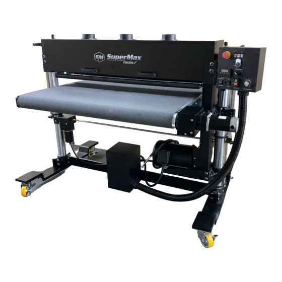
- Page 1 OWNERS’S MANUAL SuperBrush 49 Lagunatools.com...
-
Page 2: Warranty
Machines sold through dealers must be registered with Laguna Tools within 30 days of purchase to be covered by this warranty. Laguna Tools guarantees all new machine sold to be free of manufacturers’ defective workmanship, parts and materials. -
Page 3: Table Of Contents
CONTENTS Warranty: Safety: Important Safety Instructions General Safety Rules Unpacking: Assembly: Components: Power Supply: Connecting Power Wiring Diagrams Operation: Maintenance: Trouble Shooting: Exploded Views: Parts List Specifications: Supplies: LAGUNATOOLS.COM... -
Page 4: Safety
SAFETY READ AND UNDERSTAND THIS MANUAL AND ALL INSTRUCTIONS BEFORE USING THIS EQUIPMENT. Failure to follow all instructions may result in electric shock, fire and/or serious personal injury or property damage! Electronic copies of this manual are available at www.lagunatools.com SAFETY GUIDELINES - DEFINITIONS This manual contains information that is important for you to know and understand. -
Page 5: Important Safety Instructions
Woodworking, metalworking, composites, etc. (and similar materials) can be dangerous if safe and proper operating procedures are not followed. As with all machinery, there are certain hazards involved with the operation of the machine. Using the machine with respect and caution will considerably lessen the possibility of personal injury. However, if normal safety precautions are overlooked or ignored, personal injury to the operator may result. - Page 6 4. Do not use this machine for other than its intended use. If used for other purposes, LAGUNA TOOLS INC., disclaims any real or implied warranty and holds itself harmless from any injury that may result from that use.
- Page 7 • Lead from lead based paint. • Crystalline silica from bricks, cement and other masonry products. • Arsenic and chromium from chemically treated lumber. Your risk of exposure varies, depending on how often you do this type of work. To reduce your exposure to these chemicals, work in a well- ventilated area and work with approved safety equipment, such as face or dust masks/respirators that are specifically designed to filter out microscopic particles.
- Page 8 19.Keep visitors a safe distance from the work area. Keep children away. 20.Make your workshop child proof with padlocks, master switches or by removing starter keys. 21.Give your work undivided attention. Looking around, carrying on a conversation and “horse-play” are careless acts that can result in serious injury.
-
Page 9: General Safety Rules
ADDITIONAL SAFETY INFORMATION Intended use. This machine is intended for the applications discussed and approved by Laguna/SuperMax. Do not use this machine for non-approved applications or flammable, combustible, or hazardous materials. Hazardous dust. Dust created while using machinery may cause cancer, birth defects, or long-term respiratory damage. - Page 10 Wear respirator. Fine dust that is too small to be caught in the filter may be introduced into the ambient air during operation. Always wear a NIOSH- approved respirator during operation and for a short time after to reduce your risk of permanent respiratory damage. Disconnecting power supply.
- Page 11 MOTOR SPECIFICATIONS The typical main motor is 10 HP and is wired for 208-230 Volt, Three-Phase, 60 HZ, AC current. Confirm your motor electrical configuration before connecting power! Before connecting the machine to the power source, make sure the starter and switches are in the "OFF" position. Power Cord and “plug”...
-
Page 12: Unpacking
Power Supply Circuit Requirements The power source circuit for your machine must be g r o u n d e d and r a t e d f o r the a m p e r a g e given below. Never replace a circuit breaker on an existing circuit with one of higher amperage without consulting a qualified electrician to ensure compliance with wiring codes. -
Page 13: Assembly
DESCRIPTION (QUANTITY) A. Box (4 Casters & hardware) B. Owner’s Manual (1) C. CR-2032 Batteries (2) Figure 2: Casters & Hardware Report any missing or damaged parts to your dealer or distributor. Prior to machine assembly and use, read this manual thoroughly to familiarize yourself with proper assembly, maintenance and safety procedures. - Page 14 To assemble your SuperBrush 49, follow these steps: For your own safety, do not connect the machine to the power source until the machine is completely assembled. Please also make sure that you read and understand the entire manual. 1. Make sure the four locking set screws in the Table Support Casting are tight.
- Page 15 Figure 4: Attaching casters 3. Lower the machine to the floor. Table Support Set Screws (2 each side) Figure 5: Table Support Set Screws LAGUNATOOLS.COM...
- Page 16 4. Loosen the four nuts then the four set screws locking the table support casting, Fig. 5. Finger tighten these same set screws. Hold the set screw with a Hex wrench and tighten the nut. Note, these set screws are brass tipped and are designed to lightly rub on the column.
- Page 17 Hand Crank, motor Bearings (2) Shipping Arbor Mounting Bolts (2) Set Screws (2) Pulley igure 7A & B: Shipping Arbor and Bearings 8. Installing brush head; A. Install brush head (if not already installed) by removing brush head from shipping box. B.
- Page 18 9. Check alignment (parallelism) of the brush head to the conveyor. Measure from the bottom of the brush bristles to the top of the conveyor belt on the right and left side. If the brush head is not parallel; A. loosen the two bearing bolts (that secure the bearing to the machine) on the lower side of the brush, Fig.
-
Page 19: Components
COMPONENTS Emergency Stop Motor Raising Handle (behind Conveyor Height Control Panel) (manual) Control Panel Tension Rollers (See Fig. 12) Conveyor Conveyor Motor Conveyor Lift Motor Main Motor Figure 10: Main Components of SuperBrush 49 NOTE: Assembly is continued in next section “Power Supply” LAGUNATOOLS.COM... -
Page 20: Power Supply
POWER SUPPLY Power Supply Circuit Requirements The power source circuit for your machine must be g r o u n d e d and r a t e d f o r the a m p e r a g e given below. Never replace a circuit breaker on an existing circuit with one of higher amperage without consulting a qualified electrician to ensure compliance with wiring codes. - Page 21 NOTE: A “plug” and cord are NOT included and must be installed by a qualified technician/electrician or the power cable connected (hard wired) to an appropriate disconnect according to local codes. A qualified electrician should do the connection. When completed, the machine must conform to the National Electric Code and all local codes and ordinances.
- Page 22 FUNCTION, Control Panel Back Motor Height Adjustment Conveyor High Speed Adjustment Figure 13: Control Panel Components (Back) NOTE: The speed of “High Speed” Conveyor lifting can be adjusted on the back of control panel with a rotating stud. LAGUNATOOLS.COM...
-
Page 23: Wiring Diagrams
WIRING DIAGRAMS POWER CONNECTIONS Figure 14: Power Connections & Wiring LAGUNATOOLS.COM... - Page 24 INTERNAL WIRING Figure 15: Internal Wiring LAGUNATOOLS.COM...
-
Page 25: Operation
OPERATION 1. Confirm brush head is parallel to conveyor bed. See Page 17, “Checking Parallelism” to adjust if necessary. 2. Confirm the electrical supply is correct and connected to machine. 3. Make sure no one is working on or doing maintenance to machine. 4. - Page 26 5. Confirm correct contact of hold-down (pressure) rollers. Adjust contact by loosening the roller bracket in each corner and raising or lowering to provide proper tension. Correct tension is achieved when material feeds through brush properly without slipping on the conveyor belt. Tension Roller Adj.
- Page 27 Figure 19: DRO calibration 7. To start brush, press the “FRONT BRUSH” “ON” button on the front of the Control Panel, (Fig. 19 & 39). Confirm brush rotation is correct for application and material. If not correct, press OFF button, wait for machine to stop.
- Page 28 NOTE: Conveyor belt will require (periodic) adjustment to maintain proper tacking on conveyor bed. Adjust by tightening the adjustment stud, Fig. 21, with a 5mm Hex Wrench) on the side the belt is drifting toward and loosen the opposite side an equal rotation. NOTE: Make adjustments before conveyor belt rubs on side of conveyor bed.
-
Page 29: Maintenance
The EMERGENCY STOP button should only be used for an Emergency! It disconnects all power to the machine during an Emergency. It should not be used as the normal shut down procedure and it should not be used when conducting maintenance. Power should be positively disconnected to the machine for maintenance or repairs. -
Page 30: Exploded Views
Exploded Views STAND ASSEMBLY Figure 22: Stand Assembly LAGUNATOOLS.COM... -
Page 31: Parts List
Stand Assembly Parts List Ref. Part Description Size Qty. 1 ..31-0020 ....HANDLE, SWIVEL ASSY ............... 1 2 ..20-0772 ....ROLL PIN ..............3/16"X1" ....1 3 ..50-3080 ....OILITE WASHER ............ 5/8” I.D....2 4 .. - Page 32 Ref. Part Description Size Qty. 54 ..BB-R8ZZ ....BEARING ..............R8ZZ ...... 4 55 ..93267-2-155 ..SPACER ....................1 56 ..10-8802 ....SET SCREW ............5/16”-18X1/4”..14 57 ..93497-157 .... DC GEAR MOTOR ..........180VDC ....1 59 ..
- Page 33 HEAD ASSEMBLY Figure 23: Head Assembly (without brush) LAGUNATOOLS.COM...
- Page 34 Head Assembly Parts List Ref. Part Description Size Qty. 1 ..40-3250 ....DUST COVER ..................1 2 ..80-2841 ....HANDLE, DUST COVER ............... 2 3 ..913002-121 ..SOCKET HEAD BUTTON SCREW ......3/8”-16X1-1/4” ..8 4 ..11-0104 ....FLAT WASHER ............3/8”X20X2t .... 8 5 ..40-0613 ....
- Page 35 CONVEYOR ASSEMBLY Figure 24: Conveyor Assembly LAGUNATOOLS.COM...
- Page 36 CONTROL PANEL ASSEMBLY (Incl. w/Conveyor Parts) Figure 25: Control Panel Assembly (Included with Conveyor parts list) LAGUNATOOLS.COM...
- Page 37 VFD & POWER IN ASSEMBLY (Incl. w/Conveyor Parts) Figure 26: VFD & Power-In Assembly (included with Conveyor parts list) LAGUNATOOLS.COM...
- Page 38 Conveyor Assembly Parts List, includes Control Box & VFD Ref. Part Description Size Qty. 1 ..635DS-361 ... EMERGENCY STOP LABEL ..............1 2 ..93267-2-302 ..EXTERNAL TOOTH LOCK WASHER ....M4......2 3 ..93497-2-303 ..CONTROL BOX SUPPORT BRACKET ..........1 4 ..93497-2-304 ..
- Page 39 Ref. Part Description Size Qty. 54 ..11-0104 ....FLAT WASHER ............3/8”X20X2t ..14 55 ..61-1017 ....BELT, CONVEYOR POLYURETHANE ..........1 56 ..93267-2-356 ........... 1 CONTROLLER, 180 VDC, VARIABLE SPEED, CONVEYOR 57 ..72-6202-1 ..... FUSE HOLDER ..................1 58 ..10-3803 ....
-
Page 40: Specifications
(L x W x H) (1829 x 1118 x 1422 mm) Machine weight: 754 lbs. (342 kg.) Shipping weight: 1135 lbs. (515 kg.) SUPPLIES: Conveyor Belt # 61-1017 Various brush heads # varies Contact Laguna Tools for supplies : Ph: 800.234.1976 www.lagunatools.com LAGUNATOOLS.COM... - Page 41 NOTES LAGUNA TOOLS LAGUNATOOLS.COM...
- Page 42 7291 Heil Avenue Huntington Beach, CA 92647 Ph: 800.234.1976 www.lagunatools.com 100820 LAGUNATOOLS.COM...
Need help?
Do you have a question about the SuperMax SuperBrush 49 and is the answer not in the manual?
Questions and answers