Table of Contents
Advertisement
Quick Links
Functional Summary
®
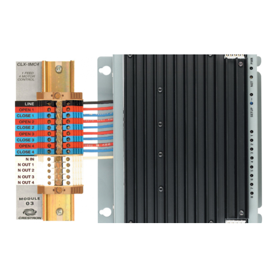
The Crestron
1-Feed, 4-Motor Terminal Block and
Module (CLT-1MC4 and CLX-1MC4, respectively), are
considered a single entity and must be used together.
They ship separately to permit termination of the field
wiring to the CLT-1MC4 prior to installation of the CLX-
1MC4, as described in this guide. They can be mounted in
any Crestron Automation Enclosure (CAEN-Series
Enclosures). The terminal block is designed to terminate
the circuit feed (HOT and NEUTRAL) and distribute the
controlled circuits (LOAD) to the motors. The module
connects to the terminal block and performs control of
four bi-directional motors. The maximum load is 10 amps
(1/2 HP) for any controlled circuit, limited to 16 amps
total per module. The unit requires 120VAC 50/60 Hz, 1
phase input voltage. An oversize heat sink dissipates heat
efficiently. There are LEDs on the module to indicate
communication to a Cresnet
module, and output power to the load.
Industry Compliance
This product is Listed to applicable UL Standards and
requirements by Underwriters Laboratories Inc.
Installation
Terminal block and module must be mounted into a
Crestron Automation Enclosure by a licensed electrician,
in accordance with all national and local codes.
CAUTION: This equipment is for indoor use only and
needs to be air-cooled. Mount in a well-ventilated area.
The ambient temperature must be 32°F to 104°F (0°C to
40°C). The relative humidity must be 0% to 90% (non-
condensing).
Terminal blocks are installed along the left side of single-
wide enclosures and along the outside edges (left and
right sides) of double-wide enclosures. Modules are
installed along the right side of single-wide enclosures
and side-by-side in the center of double-wide enclosures.
When installing modules and terminal blocks in a double-
wide enclosure, be sure to invert units on the right side so
that they can be properly wired. Refer to the illustrations
shown in the next column when considering the location
of terminal blocks and modules within an enclosure.
Crestron Electronics, Inc.
15 Volvo Drive Rockleigh, NJ 07647
Tel: 888.CRESTRON
Fax: 201.767.7576
www.crestron.com
®
network, input power to the
(E103692)
CLT- & CLX-1MC4
NOTE: Modules and terminal blocks must be
installed into the lowest available spaces and
continue toward the top of the enclosure.
Terminal Block & Module Locations (Single-wide Enclosure)
GROUNDING
TERMINAL
TERMINAL
BLOCK
BLOCK
Terminal Block & Module Locations (Double-wide Enclosure)
TERMINAL BLOCK
(LEFT)
GROUNDING TERMINAL BLOCKS
Installation Guide – DOC. 5991B
MODULE
MODULE
TERMINAL BLOCK
(RIGHT)
(2002073)
Specifications subject to
change without notice.
01.06
Advertisement
Table of Contents

Related Manuals for Crestron CLT-1MC4

Summary of Contents for Crestron CLT-1MC4
- Page 1 They ship separately to permit termination of the field wiring to the CLT-1MC4 prior to installation of the CLX- 1MC4, as described in this guide. They can be mounted in any Crestron Automation Enclosure (CAEN-Series Enclosures).
- Page 2 If you require a UL Listed panel, Crestron offers this service through its UL Listed panel shop. This includes complete in factory system configuration and assembly by Crestron for an additional fee.
- Page 3 4. Turn on the circuit breaker and verify that the green PWR LED on the module lights and the breaker does not trip. Installation Guide – DOC. 5991B Wiring Diagram of the Terminal Block to the Module (Single-wide and Left Side Double-wide Enclosures) BLACK BLUE...
- Page 4 CRESTRON shall not be liable to honor the terms of this warranty if the product has been used in any application other than that for which it was intended, or if it has been subjected to misuse, accidental damage, modification, or improper installation procedures.
Need help?
Do you have a question about the CLT-1MC4 and is the answer not in the manual?
Questions and answers