Table of Contents
Advertisement
Quick Links
Operation & Installation Instructions
LB4 Series
NSF/ANSI Standard 55 Class A
System Tested and Certified by
NSF International against CSA
B483.1 and NSF/ANSI 55
for Disinfection Performance, Class A
C
US
System
Rated Flow
System
LB6-02XA
1.6 gpm
LBH6-05XA
LB6-03XA
2.2 gpm
LBH6-10XA
LB6-06XA
3.4 gpm
LBH6-15XA
LB6-10XA
6.3 gpm
LBH6-25XA
LB6-15XA
7.9 gpm
LBH6-40XA
illuminating technologies for life
LBH4 Series
NSF/ANSI Standard 55 Class B
C
US
Rated Flow
System
Rated Flow
LB5-02XB
2.2 gpm
2.9 gpm
LB6-02XB
4.1 gpm
LB5-03XB
5.2 gpm
LB6-03XB
5.4 gpm
LB5-06XB
7.9 gpm
7.6 gpm
LB6-06XB
18 gpm
LB5-10XB
13 gpm
LB6-10XB
LB5-15XB
22 gpm
LB6-15XB
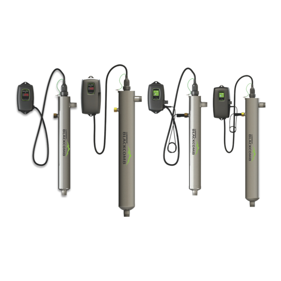
BLACKCOMB
OWNER'S MANUAL
LB5 Series
LB6 Series
System Tested and Certified by
NSF International against CSA
B483.1 and NSF/ANSI 55
for Disinfection Performance, Class B
System
Rated Flow
LBH5-05XB
5.4 gpm
LBH6-05XB
LBH5-10XB
7.6 gpm
LBH6-10XB
LBH5-15XB
13 gpm
LBH6-15XB
LBH5-25XB
22 gpm
LBH6-25XB
LBH5-40XB
28 gpm
LBH6-40XB
LBH5 Series
LBH6 Series
LUMINOR - Standard Systems
Rated
System
System
Flow
LB4-021
LBH4-051
2
LB5-021
LBH5-051
gpm
LB6-021
LBH6-051
LB4-031
LBH4-101
3
LB5-031
LBH5-101
gpm
LB6-031
LBH6-101
LB4-061
LBH4-151
6
LB5-061
LBH5-151
gpm
LB6-061
LBH6-151
LB4-101
LBH4-251
11
LB5-101
LBH5-251
gpm
LB6-101
LBH6-251
LB4-151
LBH4-401
15
LB5-151
LBH5-401
gpm
LB6-151
LBH6-401
LB4-201
21
LB5-201
gpm
LB6-201
Rated
Flow
5 gpm
10
gpm
15
gpm
25
gpm
40
gpm
Advertisement
Table of Contents

Related Manuals for Luminator BLACKCOMB LB4 Series

Summary of Contents for Luminator BLACKCOMB LB4 Series
- Page 1 BLACKCOMB OWNER’S MANUAL Operation & Installation Instructions LB4 Series LBH4 Series LB5 Series LBH5 Series LB6 Series LBH6 Series NSF/ANSI Standard 55 Class A NSF/ANSI Standard 55 Class B LUMINOR - Standard Systems Rated Rated System System System Tested and Certified by System Tested and Certified by Flow Flow...
- Page 2 Congratulations on purchasing this ultraviolet disinfection system. By purchasing a LUMINOR UV Disinfection system you are receiving not only a high quality product but also peace of mind. Installing a UV system gives you reassurance that the water in your home will have an extra level of protection.
-
Page 3: Table Of Contents
TABLE OF CONTENTS Safety Considerations ......................4 Before You Begin ........................ 4 Water Quality Parameters ....................5 Assembly ..........................6 System Sizing ........................8 Location ..........................8 Installation ......................... 9 System Disinfection ......................12 Cleaning the Quartz Sleeve ....................12 Cleaning the UV Sensor .................... -
Page 4: Safety Considerations
Safety Considerations It is important that care is taken when operating and/or maintaining your system. 1. Before servicing this equipment, disconnect the power cord from the electrical outlet. 2. Energy given off by the UV lamp is harmful to your eyes and skin. NEVER look directly at an illuminated UV lamp without adequate eye protection and always protect your skin from direct exposure to the UV light. -
Page 5: Water Quality Parameters
Water Quality Parameters UV disinfection is only effective if the UV light can pass through the water it needs to treat. This means that the quality of your water is very important in order to ensure complete disinfection. Treated water should be tested for at the least the parameters listed below. If the water exceeds the listed parameters LUMINOR strongly recommends that appropriate pretreatment equip- ment be installed (equipment required will depend on parameters being treated): Hardness:... -
Page 6: Assembly
Assembly Unpack the system and ensure all the components are included with the system. Your system is shipped with the following components: BLACKCOMB (Standard output lamp systems) LAMP KEY GLAND NUT CONTROLLER 320006 4.1 SYSTEMS O-RING RC-B4.01 5.1/6.1 SYSTEMS 300038 RC-B56.01 UV LAMP RL-210- “-02”... - Page 7 BLACKCOMB-HO (High output lamp systems) LAMP KEY GLAND NUT CONTROLLER 320006 4.1 SYSTEMS O-RING RCHO-B4.12 300038 (fits all units) 5.1/6.1 SYSTEMS UV LAMP RCHO-B56.12 RL-210HO “-05” series (fits all units) RL-330HO “-10” series RL-420HO “-15” series RL-600HO “-25” series RL-950HO “-40” series GLOW PLUG (BLACKCOMB units only)
-
Page 8: System Sizing
System Sizing All LUMINOR UV systems are rated for a specific flow rate in water that meets the quality param- eters on page 5. PLEASE NOTE that increasing the flow above this rating or disinfecting water that does not meet the quality parameters will decrease the dose and therefore compromise the efficacy of the system. -
Page 9: Installation
Installation Step 1: The reactor can be installed either horizontally or vertically using the clamps provided. Vertical installation is the preferred method with the inlet at the bottom (lamp connection at the top) as it allows any air that may be in the lines to be easily purged from the system. - Page 10 Step 6: Once the system has been plumbed in, gently remove the quartz sleeve from its packaging being careful not to touch the length with your hands. The use of cotton gloves is recommended for this procedure as oils from the hands can leave residue on the sleeve and lamp which can ultimately block the UV light from getting to the wa- ter.
- Page 11 Step 11: Always hold UV lamps by their ceramic ends, not by the lamp quartz. Remove the lamp from its packaging. Again, the use of cotton gloves is recommended. Remove the lamp key from the lamp’s connector and set it aside for the next step. Be careful to not touch the key’s exposed contacts.
-
Page 12: System Disinfection
System Disinfection With a new installation, or any time the UV system is shut down for service, without power, or is inoperative for any other reason, the lines in the home or facility could be contaminated. Use the following steps to fully disinfect the lines throughout the entire home or facility. Step 1: Check for and remove any “dead ends”... -
Page 13: Cleaning The Uv Sensor
Step 10: Dry the sleeve with separate cloth. Step 11: Replace the o-ring and slide the sleeve back into the reactor following steps 7 and 8 from the installation section of the manual. Cleaning the UV Sensor Depending on the water quality, the UV sensor may require periodic cleaning. At a minimum, the UV sensor should be cleaning on an annual basis. -
Page 14: Blackcomb 4.1 Controllers
BLACKCOMB Controllers Simplistic in operation, these systems feature a tri-colour LED that indicating system status and a 4-digit display to in- dicate lamp life remaining. Pressing the button will change the display to indicate total running time. When the UV lamp is on and within its operating age, the LED will be green. -
Page 15: Blackcomb 5.1 Operational Screens
A final module screen is displayed showing which specific modules were initialized. The controller then displays the lamp optimization screen for 60 seconds to allow the lamp to reach its optimum output. Finally, a final “start-up complete” screen is displayed. The system will now be ready to disinfect water flow. -
Page 16: Lamp Countdown Sequence
audible chirp every audible chirp every constant audible cycles with red low 15 seconds 15 seconds alarm UV screen Lamp Countdown Sequence The system counts down the number of days until a lamp change is required. BLACKCOMB BLACKCOMB BLACKCOMB At thirty days remaining, the LED or display screen will change to a yellow caution indicator. At seven days remaining, the system will additionally repeat an audible chirp. -
Page 17: System Service Suggested
System Service Suggested BLACKCOMB 5.1 & 6.1 controllers will display the System Service Suggested Screen every 6 months to remind consumers to maintain both their UV and other prefiltration. This will serve as a prompt only and will not put the system into alarm. -
Page 18: System Troubleshooting
System Troubleshooting Hard Alarms: The following give a constant audible alarm. If present, the solenoid valve is closed, and the 4-20, remote alarm and wifi modules transmit the alarm. System Display Problem Resolution Reset lamp protection circuit -unplug unit for 10 seconds. The system has detected Replace the lamp with the a problem with the... - Page 19 Soft Alarms: The following remaining errors give a 15 second audible chirp only System Display Problem Resolution Ensure all modules are connected properly to the system and to each other. The module Modules can be tested indicated is no longer individually by plugging in communicating to with one at a time and cycling...
-
Page 20: Temperature Management Devices
Temperature Management Devices Your LUMINOR BLACKCOMB system is designed to run continuously to ensure optimal disinfection. However, during periods when no water is drawn through the system, the energy from the disinfection process can cause the temperature of the water inside the chamber to rise. In extreme situations elevated water temperature or the fluctuation in temperature can lower the output of the UV lamp. - Page 21 SOLENOID CONNECTION MODULE: Connects a NORMALLY CLOSED line voltage solenoid valve to the controller. Maximum contact rating is 240VAC (50-60Hz) / 30VDC / 2A. On a non-monitored sys- tem, the solenoid will only close on a lamp fail- ure error. On a monitored system, the solenoid is closed when the UV level drops below 50%.
-
Page 22: Blackcomb Standard Output System Specifications
BLACKCOMB Standard Output System Specifications LUMINOR EQUIPMENT SPECIFICATIONS Residential systems (standard output lamps) Multi-Use / LB4-021 LB4-031 LB4-061 LB4-101 LB4-151 LB4-201 MODEL LB5-021 LB5-031 LB5-061 LB5-101 LB5-151 LB5-201 LB6-021 LB6-031 LB6-061 LB6-101 LB6-151 LB6-201 1.6 gpm 2.2 gpm 3.4 gpm 6.3 gpm 7.9 gpm NSF Class A Flow Rate... -
Page 23: Blackcomb-Ho High Output System Specifications
BLACKCOMB-HO High Output System Specifications LUMINOR EQUIPMENT SPECIFICATIONS Residential Crossover systems (high output lamps) LBH4-05X LBH4-10X LBH4-15X LBH4-25X LBH4-40X MODEL LBH5-05X LBH5-10X LBH5-15X LBH5-25X LBH5-40X LBH6-05X LBH6-10X LBH6-15X LBH6-25X LBH6-40X 2.2 gpm 4.0 gpm 5.4 gpm 7.9 gpm 18 gpm NSF Class A Flow Rate 40mJ/cm @ 70% UVT... -
Page 24: Performance Data Sheet (On All Nsf/Ansi Standard 55, Class A Systems)
Performance Data Sheet (on all NSF/ANSI Standard 55, Class A Systems) System Tested and Certified by NSF International against CSA B483.1 and NSF/ANSI 55 for Disinfection Performance, Class A LB6-02XA LB6-03XA Model LB6-06XA LB6-10XA LB6-15XA LBH6-05XA LBH6-10XA LBH6-15XA LBH6-25XA LBH6-40XA LB6-02A-12V LB6-03A-12V LB6-02A-24V... -
Page 25: Performance Data Sheet (On All Nsf/Ansi Standard 55, Class B Systems)
Performance Data Sheet (on all NSF/ANSI Standard 55, Class B Systems) System Tested and Certified by NSF International against CSA B483.1 and NSF/ANSI 55 for Disinfection Performance, Class B LB5-06XB LB5-10XB LB5-15XB LBH5-05XB LBH5-10XB LBH5-15XB LBH5-25XB LBH5-40XB Model LB5-03XB LB6-06XB LB6-10XB LB6-15XB LBH6-06XB... -
Page 26: Limited Warranty Statement
Limited Warranty Statement: Products manufactured by LUMINOR Environmental Inc., (LUMINOR) are warranted to the origi- nal user only to be free of defects in material and workmanship for a period as specified below. This warranty only applies to the original purchaser and is not transferable. UV SYSTEMS Ten (10) year Limited Warranty on the stainless steel reactors, from the date of original purchase, or installation (proper documentation required for verification). -
Page 27: Warranty Registration
TO GET WARRANTY SERVICE To obtain service under this warranty, you must first contact LUMINOR Customer Service at 855- 837-3801 (519-837-3800 outside of the US or Canada) to obtain a Warranty Return Authoriza- tion. You will then need to return the product through the LUMINOR Dealer or Distributor where the product was originally purchased, together with proof of purchase and installation date, failure date, and supporting installation data. - Page 28 illuminating technologies for life 80 Southgate Drive, Unit 4 See manual Guelph, Ontario, CANADA N1G 4P5 in French: P: 519-837-3800 TF: 855-837-3801 F: 519-837-3808 info@luminoruv.com www.luminoruv.com EPA Establishment #088776-CAN-001 PN#910001 Version Date: 06-2021...
Need help?
Do you have a question about the BLACKCOMB LB4 Series and is the answer not in the manual?
Questions and answers