Table of Contents
Advertisement
Advertisement
Table of Contents

Related Manuals for Geutebruck G-ST 6000+ G2


Summary of Contents for Geutebruck G-ST 6000+ G2
- Page 1 G-ST 6000+ G2 Installation manual...
-
Page 2: Introduction
Please read and observe these operating instructions so that errors and danger can be avoided. The operating instructions are valid for the G-ST 6000+ G2. The operating instructions are only valid when the device corresponds to the version described herein. -
Page 3: Table Of Contents
Turning on the device ................14 Integrating the device into the network ............. 16 Working with the G-ST 6000+ G2 ............ 17 Overview ....................17 Using the online documentation ............... 19 Managing I/O contacts ................20 ... -
Page 4: General Notes And Safety
General notes and safety General notes and safety Intended use The G-ST 6000+ G2 is a high performance, digital video management system based on modern processor architectures. The G-ST 6000+ G2 supports direct recording and playback of network cameras. The recording rate depends on the type of network camera. -
Page 5: General Safety Instructions
General notes and safety General safety instructions When using the devices or performing maintenance on them, the following safety in- structions are to be observed to protect the operator, the service technician and the device: During design and construction of the devices, the acknowledged state of the art as well as the acknowledged applicable standards and directives have been taken into account and implemented. -
Page 6: Transportation, Storage, Initial Commissioning
The device may only be commissioned after it has been ensured that all applica- ble safety requirements have been fulfilled. Scope of delivery Ensure that the following items are included in the delivery: G-ST 6000+ G2 Manual ... -
Page 7: Device Description
Device description Device description Overview of G-ST 6000+ G2 Recommended uses and applications The G-ST 6000+ G2 is a high availability, redundant system platform for use in large branches. Due to the flexible expandability with a wide range of software... -
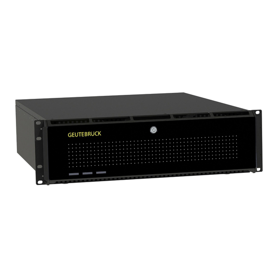
Page 8: Device View
Device description Device view Front view Figure 1: Front view Figure 2: Front view without cover LED (white) Power LED (red) Error LED (white) Record HDD USB (2x) Action pushbutton (finger actuated) Reset pushbutton (pin actuated) Power pushbutton (pin actuated) Alarm Reset pushbutton (pin actuated) LED (yellow) HDD in use LED (white) Fan error... -
Page 9: Rear View G-St 6000+ G2
Device description Rear view G-ST 6000+ G2 Figure 3: Rear view G-ST 6000+ G2 Mains Power supply Control inputs for connecting external contacts for the event-based image recording/relay outputs Connection for PS/2 PC keyboard (6-pin mini-DIN socket) Connection for PS/2 PC mouse (6-pin mini-DIN socket) USB 2.0 interfaces (2x) -
Page 10: Hard Disk Drive Carrier
Device description Hard Disk Drive Carrier Power LED continuous green light when disk in and power on Access LED S-ATA: no light in idle mode, blinking blue light when access Failure/ Rebuiling LED Failure: continuous red light Rebuilding: blinking red light when the specific disk is build in a degraded array Handle lock pressing it to the left unlocks the drive from the bay... -
Page 11: Removing The Disk Drive Carrier
Device description Removing the disk drive carrier Disk drives could be removed when system is off, but also when system is running (Hot Plug). This only should be done in case of a disk failure. Do not pull out disks during system is running, when there is no disk failure. -
Page 12: Changing A Redundant Power Supply
Device description Changing a Redundant Power Supply A power supply could be removed when system is off, but also when system is run- ning (Hot Plug). This only should be done in case of a power supply failure. Remove power cord from back of the power... -
Page 13: Installation And Commissioning
Installation and commissioning Requirements Checking the conditions Before you integrate your G-ST 6000+ G2 into an existing network, you must en- sure that the following conditions are met: There is a functioning network with TCP/IP protocol (100/1000 Mbit Ethernet). -
Page 14: Preparations
Windows directory. For connecting external devices, note in general: G-ST 6000+ G2 devices do not have a CD-ROM/DVD drive. When selecting de-vices, please ensure that the devices are compatible with MS Windows. -
Page 15: Connecting Devices
Installation and commissioning Connecting devices All connections are made on the back. In addition, two USB ports are available on the front. Please note the following precautions for your security and the safety of the appli- ance. Warning! All connection work may only be performed when the device is shut off. ... - Page 16 Installation and commissioning Enter the following at the MS windows Logon dialog box: User name: Administrator Password: Pa$$w0rd Please confirm by pressing the ENTER key. The Admin user profile allows full access to your G-ST. You are now on the operating system level. At first, please choose your language setting.
-
Page 17: Integrating The Device Into The Network
Installation and commissioning 2. Select a language and click "Next". The corresponding language pack is in- stalled. 3. Open the Region and Language options, by clicking Start , Control Panel and then Language. 4. Click Add a Language to access the selection menu. Select your language and click "Add". -
Page 18: Working With The G-St 6000+ G2
Working with the G-ST 6000+ G2 Working with the G-ST 6000+ G2 Overview After the G-ST has been started and successfully integrated into a network, you can work with the device. The G-ST uses the following applications which can be opened using the start bar or from the desktop using a double click: ... - Page 19 Working with the G-ST 6000+ G2 In G-Set, you will perform, among others, the following tasks to set up the system: Register all IP cameras that are integrated in the network with your G-ST. Set up the media channels. For each media channel the quality profile is de- termined for permanent recording and live streaming.
-
Page 20: Using The Online Documentation
Working with the G-ST 6000+ G2 Using the online documentation Online All necessary functions for set up and configuration of the system are described in the G-Set Online help. You will also find the details of the G-View operating compo- documentation nent. -
Page 21: Managing I/O Contacts
Assigning contacts Digital inputs The G-ST 6000+ G2 has 16 control inputs, which are each equipped with an internal pull-up resistor with 1 kΩ to +5 V. The control inputs are distributed onto two 25-pin Sub-D sockets (inputs 1-8 and 9-16. - Page 22 Working with the G-ST 6000+ G2 Digital outputs Each unit has four floating digital outputs. Like the digital inputs, these are distrib- uted onto the 25-pin sub-D socket (relay 1-4). Using the digital outputs, you can switch external devices, for example, to report sys- tem errors.
-
Page 23: Adding I/O Contacts In G-Set
Working with the G-ST 6000+ G2 Adding I/O contacts in G-Set Similar to the cameras, I/O contacts must also be registered using the G-Set soft- ware. The I/O connections are displayed in the list of hardware modules. Configura- tion is performed in a separate view. -
Page 24: Using Other Connections
Working with the G-ST 6000+ G2 Using other connections Analog Video Connections (optional) Figure 5: AnalogKit-H16 BNC input sockets and Audio Line In Connect FBAS cameras or other FBAS signal sources to the BNC input sockets of the video inputs "VID1", "VID2" etc. -
Page 25: Additional External Connections
Working with the G-ST 6000+ G2 Additional external connections The following external connections are available on the rear of the device: PS2-ports PS2-Keyboard and Mouse can be connected to their PS2 port. Figure 7: PS2 ports USB (2.0 / 3.0 / 3.1) ... -
Page 26: Turning Off The Device
Working with the G-ST 6000+ G2 Audio An audio source can be connected at the soundcard ports. Line in Line out Figure 11: Audio connections COM1 At the COM1 port, there is a RS-232 interface via a 9-pin Sub-D socket. -
Page 27: Resetting The System To Factory Settings
Resetting the system to factory settings Resetting the system to factory settings Recovery DVDs are provided with your device. This allows for the recovery of the software in- stalled at delivery as well as the original settings. Please note that the recovery process should only be carried out by qualified personnel, as all data on the C:\ drive will be overwritten! Back up your settings on an external disk beforehand. - Page 28 Resetting the system to factory settings 6. In the menu "Troubleshoot" click on the menu button " GEUTEBRUECK Recovery Solution ". 7. Select the size of the Windows partition, click RECOVERY START 8. Confirm disk partition by clicking YES. Now the system recovery starts. During the recovery process, the device may be rebooted several times.
-
Page 29: Appendix Technical Data
Appendix Technical Data Appendix Technical Data Operating System Windows 10 IoT Enterprise Number of slots 8x HDD, 1x SSD Intel Core i5, i7 or i9 inside CPU type Max. Database 450TB GPU Acceleration Analog extendable OS on seperate SSD 2 x 8 GB DDR4 Storage Interface SCSI Ethernet... - Page 30 Technical alterations reserved. GEUTEBRÜCK GmbH Im Nassen 7-9 | D-53578 Windhagen | Tel. +49 (0)2645 13 7-0 | F ax-999| E-mail: info@geutebrueck.com | Web: www.geutebrueck.com...
Need help?
Do you have a question about the G-ST 6000+ G2 and is the answer not in the manual?
Questions and answers