Table of Contents
Advertisement
Quick Links
FCC ID: K6620393X50
IC: 511B-20393X50
Alignment
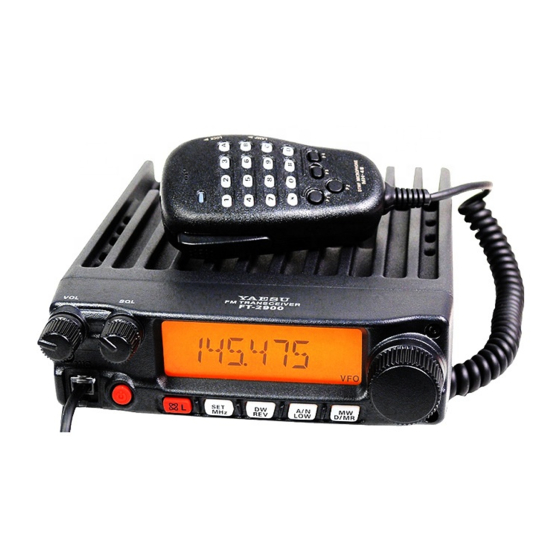
FT-2900R Alignment
Introduction
The FT-2900R is carefully aligned at the factory for the specified performance across
the amateur band. Realignment should therefore not be necessary except in the event
of a component failure. Only an authorized Vertex Standard representative should
perform all component replacement and service, or the warranty policy may be void.
The following procedures cover the adjustments that are not normally required once
the transceiver has left the factory. However, if damage occurs and some parts
subsequently are replaced, realignment may be required. If a sudden problem occurs
during normal operation, it is likely due to component failure; realignment should not
be done until after the faulty component has been replaced.
We recommend that servicing be performed only by authorized Vertex Standard service
technicians who are experienced with the circuitry and fully equipped for repair and
alignment. If a fault is suspected, contact the dealer from whom the transceiver was
purchased for instructions regarding repair. Authorized Vertex Standard service
technicians realign all circuits and make complete performance checks to ensure
compliance with factory specifications after replacing any faulty components.
Those who do undertake any of the following alignments are cautioned to proceed at
their own risk. Problems caused by unauthorized attempts at realignment are not
covered by the warranty policy. Also, Vertex Standard reserves the right to change
circuits and alignment procedures in the interest of improved performance, without
notifying owners.
Under no circumstances should any alignment be attempted unless the normal
function and operation of the transceiver are clearly understood, the cause of the
malfunction has been clearly pinpointed and any faulty components replaced, and
realignment determined to be absolutely necessary.
Required Test Equipment
The following test equipment (and familiarity with its use) is necessary for complete
realignment. Correction of problems caused by misalignment resulting from use of
improper test equipment is not covered under the warranty policy. While most steps do
not require all of the equipment listed, the interactions of some adjustments may
require that more complex adjustments be performed afterwards.
Do not attempt to perform only a single step unless it is clearly isolated electrically
from all other steps. Have all test equipment ready before beginning and, follow all of
1
Vertex Standard Co.,Ltd.
Advertisement
Table of Contents

Related Manuals for Vertex Standard FT-2900R


Summary of Contents for Vertex Standard FT-2900R
- Page 1 FT-2900R Alignment Introduction The FT-2900R is carefully aligned at the factory for the specified performance across the amateur band. Realignment should therefore not be necessary except in the event of a component failure. Only an authorized Vertex Standard representative should perform all component replacement and service, or the warranty policy may be void.
- Page 2 Note: Signal levels in dB referred to in the alignment procedure are based on 0dBµ = 0.5µV. Test Setup Set up the test equipment as shown below for transceiver alignment. Entering the Alignment Mode Alignment of the FT-2900R is performed using a front panel software-based procedure. Vertex Standard Co.,Ltd.
- Page 3 Inject a 145.100 MHz signal at a level of –5 dBµ (with 1 kHz modulation @±3.5 kHz deviation) from the RF signal generator. Rotate the DIAL knob to set the alignment parameter to “145.100 S1.” Press the [D/MR(MW)] key to enable adjustment of the “S-meter Level (S-1).” Vertex Standard Co.,Ltd.
- Page 4 Rotate the DIAL knob to set the alignment parameter to “145.000 L1.” Press the [D/MR(MW)] key to enable adjustment of the “TX Power (Low 1).” Press the PTT switch to activate the transmitter, adjust the DIAL knob so that the Vertex Standard Co.,Ltd.
- Page 5 Press the PTT switch to activate the transmitter, adjust the DIAL knob so that the Deviation Meter reading is 0.8 kHz (±0.05 kHz). Press the [D/MR(MW)] key. Closing the Alignment mode Press the [DW(REV)] key to save the new setting and exit to normal operation. Vertex Standard Co.,Ltd.
Need help?
Do you have a question about the FT-2900R and is the answer not in the manual?
Questions and answers