Advertisement
FCC ID: K6620305X30
IC IF: 511B-20305X30
Alignment
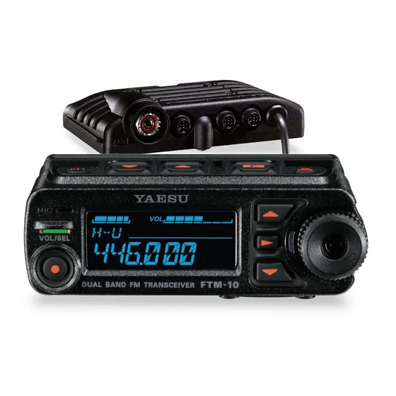
FTM-10SR Alignment
Introduction and Precautions
The FTM-10SR has been carefully aligned at the factory for the specified performance
across the 144 MHz and 430 MHz amateur bands. Realignment should therefore not be
necessary except in the event of a component failure. All component replacement and
service should be performed only by an authorized Yaesu representative, or the warranty
policy may be voided.
The following procedures cover the sometimes critical and tedious adjustments that are not
normally required once the transceiver has left the factory. However, if damage occurs and
some parts are replaced, realignment may be required. If a sudden problem occurs during
normal operation, it is likely due to component failure; realignment should not be done until
after the faulty component has been replaced.
We recommend that servicing be performed only by authorized Yaesu service technicians
who are experienced with the circuitry and fully equipped for repair and alignment.
Therefore, if a fault is suspected, contact the dealer from whom the transceiver was
purchased for instructions regarding repair. Authorized Yaesu service technicians realign all
circuits and make complete performance checks to ensure compliance with factory
specifications after replacing any faulty components.
Those who do undertake any of the following alignments are cautioned to proceed at their
own risk. Problems caused by unauthorized attempts at realignment are not covered by the
warranty policy. Also, Yaesu must reserve the right to change circuits and alignment
procedures in the interest of improved performance, without notifying owners.
Under no circumstances should any alignment be attempted unless the normal function
and operation of the transceiver are clearly understood, the cause of the malfunction has
been clearly pinpointed and any faulty components replaced, and the need for realignment
determined to be absolutely necessary.
1
Vertex Standard Co., Ltd.
Advertisement
Table of Contents

Subscribe to Our Youtube Channel
Related Manuals for Vertex Standard FTM-10SR


Summary of Contents for Vertex Standard FTM-10SR
- Page 1 FTM-10SR Alignment Introduction and Precautions The FTM-10SR has been carefully aligned at the factory for the specified performance across the 144 MHz and 430 MHz amateur bands. Realignment should therefore not be necessary except in the event of a component failure. All component replacement and service should be performed only by an authorized Yaesu representative, or the warranty policy may be voided.
- Page 2 20 °C and 30 °C (68 °C to 86 °F). When the transceiver is brought into the shop from hot or cold air it should be allowed some time for thermal equalization with the environment before alignment. If possible, alignments should be made with oscillator Vertex Standard Co., Ltd.
- Page 3 0.65-0.75 kHz on the deviation meter. DCS Deviation With the wattmeter, dummy load and deviation meter connected to the antenna jack. Key the transmitter on 146.05 (and 440.05) MHz. Adjust the frequency deviation is within 0.65-0.75 kHz on the deviation meter. Vertex Standard Co., Ltd.
- Page 4 With the dummy load and SINAD meter connected to the external speaker jack. Inject a RF signal as a level of -8 dBµV to the antenna jack. Tune the receiver on 146.05 (and 440.05) MHz. Adjust the SINAD is above 12 dB on the SINAD meter. Vertex Standard Co., Ltd.
Need help?
Do you have a question about the FTM-10SR and is the answer not in the manual?
Questions and answers