Advertisement
Quick Links
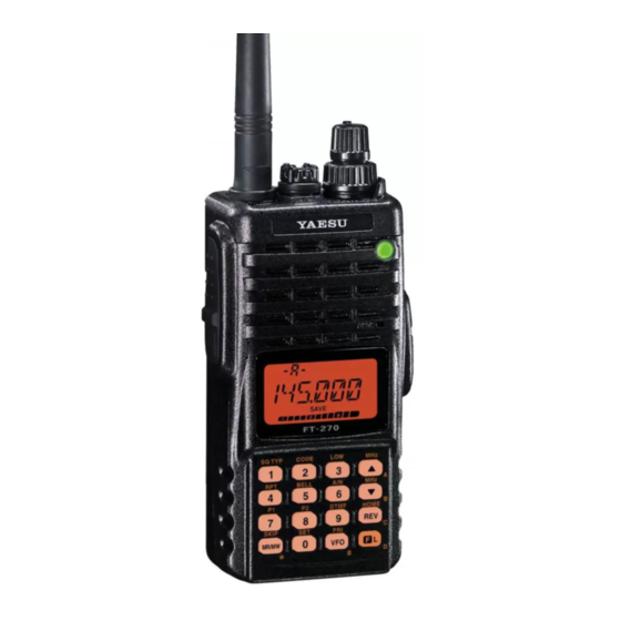
FT-270R/E
Technical Supplement
©
2010 VERTEX STANDARD CO., LTD. EH022N91B
Specifications ....................................................................................................................................................................2
Exploded View & Miscellaneous Parts .......................................................................................................................3
Block Diagram .................................................................................................................................................................. 5
Circuit Description .......................................................................................................................................................... 7
Alignment ..........................................................................................................................................................................9
Board Units (Schematics, Layouts & Parts)
Main Unit ................................................................................................................................................................... 13
FTD-7 DTMF Paging Unit (Option) ....................................................................................................................... 29
FT-270R/E Technical Supplement
Introduction
This manual provides the technical information necessary for servicing the FT-
270R/E VHF FM Transceiver.
Servicing this equipment requires expertise in handing surface-mount chip compo-
nents. Attempts by non-qualified persons to service this equipment may result in
permanent damage not covered by the warranty, and may be illegal in some coun-
tries.
Two PCB layout diagrams are provided for each double-sided board in this trans-
ceiver. Each side of the board is referred to by the type of the majority of compo-
nents installed on that side ("Side A" or "Side B"). In most cases one side has only
chip components (surface-mount devices), and the other has either a mixture of
both chip and leaded components (trimmers, coils, electrolytic capacitors, ICs, etc.),
or leaded components only.
While we believe the information in this manual to be correct, VERTEX STANDARD
assumes no liability for damage that may occur as a result of typographical or other
errors that may be present. Your cooperation in pointing out any inconsistencies in
the technical information would be appreciated.
The transceiver was assembled using Pb (lead) free solder, based on the RoHS
specification.
Only lead-free solder (Alloy Composition: Sn-3.0Ag-0.5Cu) should be used
for repairs performed on this apparatus. The solder stated above utilizes the
alloy composition required for compliance with the lead-free specification,
and any solder with the above alloy composition may be used.
Risk of explosion if battery is replaced by an incorrect type. Dispose of used
batteries according to the instructions.
Contents
VERTEX STANDARD CO., LTD.
4-8-8 Nakameguro, Meguro-Ku, Tokyo 153-8644, Japan
VERTEX STANDARD
US Headquarters
10900 Walker Street, Cypress, CA 90630, U.S.A.
YAESU UK LTD.
Unit 12, Sun Valley Business Park, Winnall Close
Winchester, Hampshire, SO23 0LB, U.K.
VERTEX STANDARD HK LTD.
Unit 5, 20/F., Seaview Centre, 139-141 Hoi Bun Road,
Kwun Tong, Kowloon, Hong Kong
VERTEX STANDARD ( AUSTRALIA ) PTY., LTD.
Normanby Business Park, Unit 14/45 Normanby Road
Notting Hill 3168, Victoria, Australia
Important Note
CAUTION
1
Advertisement

Subscribe to Our Youtube Channel
Related Manuals for Vertex Standard Yaesu FT-270R/E


Summary of Contents for Vertex Standard Yaesu FT-270R/E
-
Page 1: Table Of Contents
(trimmers, coils, electrolytic capacitors, ICs, etc.), or leaded components only. While we believe the information in this manual to be correct, VERTEX STANDARD assumes no liability for damage that may occur as a result of typographical or other errors that may be present. -
Page 2: Specifications
Specifications General Frequency Ranges: 137 (136) - 174 MHz 144 - 146 (148) MHz Channel Steps: 5/10/12.5/15/20/25/50/100 kHz Frequency Stability: ±5 ppm @ –14° to +140° F (–10° to +60° C) Repeater Shift: ±600 kHz Emission Type: F2D , F3E Antenna Impedance: 50-ohm Rating:... -
Page 3: Exploded View & Miscellaneous Parts
Exploded View & Miscellaneous Parts RA1127500 RA1113500 NAME PLATE (YAESU) WINDOW RA0304300 WASHER RA111430A DOUBLE FACE RA0577600 EXT CAP CP8221004 PANEL ASSY RA057840A RING NUT RA1113200 RA008920C PANEL O RING RA057710A RA0087900 HOLDER SPECIAL NUT RA046760A RA057700A O RING RUBBER KNOB RA1113400 RA0434100... - Page 4 Exploded View & Miscellaneous Parts Note FT-270R/E Technical Supplement...
-
Page 5: Block Diagram
Block Diagram FT-270R/E Technical Supplement... - Page 6 Block Diagram Note FT-270R/E Technical Supplement...
-
Page 7: Circuit Description
Circuit Description Receive Signal Path Transmit Signal Path Incoming RF signal is from the antenna jack is delivered The speech signal from the microphone is amplified by to the Main Unit and passed through the low-pass filter Q1074 (LM2902PWR). The amplified speech signal is sub- network, antenna switching diode D1003 and D1004 (both jected to the low-pass filter network Q1074 (LM2902PWR) RLS135), and low-pass filter network to the RF amplifier... - Page 8 Circuit Description The phase comparator section of Q1003 (MB15A01PFV1) compares the phase between the frequency-divided os- cillation frequency of the VCO circuit and comparative frequency and its output is a pulse corresponding to the phase difference. This pulse is integrated by the charge pump and loop filter of D1012 (DA221) and Q1016 (DTC144EE) into a control voltage (VCV) to control the oscillation frequency of the VCO.
-
Page 9: Alignment
We recommend that servicing be performed only by au- In-line Wattmeter with 5% accuracy at 200 MHz thorized Vertex Standard service technicians who are ex- 50-Ohm 10-W RF Dummy Load perienced with the circuitry and fully equipped for repair ... - Page 10 Alignment Test Setup Entering the Alignment Mode Set up the test equipment as shown below for transceiver Alignment of the FT-270R/E is performed using a front alignment. panel software-based procedure. To perform alignment of the transceiver, it must first be placed in the “Align- ment Mode,”...
- Page 11 Alignment RF Front-end Tuning TX Power Output 1. Connect the DC voltmeter to TP1031 on the MAIN unit, 1. Rotate the DIAL knob to select the display to “B0206,” then inject a 145.050 MHz signal at a level of +10 dBμ then set the transmit power level to “LOW.”...
- Page 12 Alignment CTCSS TX Deviation Squelch Sensitivity 1. Rotate the DIAL knob to select the display to “B0206,” 1. Rotate the DIAL knob to select the display to “B0206.” then activate the CTCSS encoder with a “100 Hz” tone, 2. Inject a 146.050 MHz signal at a level of –12 dBμV (with and set the transmit power level to “LOW.”...
-
Page 13: Main Unit
MAIN Unit Circuit Diagram TX "H": 8.10 V TX "M": 8.14 V TX "L": 8.17 V TX: 3.93 V 4.32 V TX "H": 3.04 V TX "M": 1.64 V 1.78 V TX: +18.3 dBm @146.00 MHz TX "L": 0.59 V 1.29 V TX: +6.3 dBm 1.13 V... - Page 14 MAIN Unit Note FT-270R/E Technical Supplement...
- Page 15 MAIN Unit Parts Layout (Side A) HD64F2266 (Q1001) BR24L64F (Q1002) LM2904PWR (Q1019) TDA28822 (Q1008) 2SK3476 (Q1009) 2SB1201S (Q1037) 2SA1774 (FR) 2SB1132 (BA) 2SC4617 (BR) 2SD1664 (DA) DTA144EE (16) DTC144EE (26) BD4845FVE DA221 (K) 1SS321 (F9) (Q1030, 1031, 1032, (Q1063, 1078) (Q1034, 1038, 1039, (Q1067) (Q1033, 1043, 1058,...
- Page 16 MAIN Unit Parts Layout (Side B) LM2904PWR MB15A01PFV1 2SA1774 (FR) 2SC4617 (BR) 2SJ364 (4M) 3SK296ZQ (ZQ) DTA144EE (16) DTC144EE (26) NJU7231F30 XC6202P DA221 (K) (Q1050, 1083) (Q1003) (Q1018, 1036) (Q1028, 1052, 1055, (Q1056) (Q1022, 1023) (Q1027, 1054, 1084) (Q1015, 1016, 1025, (Q1007) (Q1080) (D1012, 1030)
- Page 17 MAIN Unit Parts List DESCRIPTION VALUE TOL. MFR'S DESIG VXSTD P/N VERS. LOT SIDE LAY ADR PCB with Components CB3164015 VX-270R USA A2 CB3164016 VX-270R EXP A1 CB3164017 VX-270R EXP A2 CB3164018 VX-270R EXP A3 CB3164019 VX-270E EXP B1 CB3164020 VX-270E EXP B2 CB3164021 VX-270R EXP B3...
- Page 18 MAIN Unit Parts List DESCRIPTION VALUE TOL. MFR'S DESIG VXSTD P/N VERS. LOT SIDE LAY ADR C 1069 CHIP CAP. 0.001uF GRM155B11H102KA01D K22178809 C 1070 CHIP CAP. 0.047uF GRM155B11A473KA01D K22108801 C 1071 CHIP CAP. 47pF GRM1552C1H470JZ01D K22178228 C 1072 CHIP TA.CAP. 10uF TEESVA1A106M8R K78100028...
- Page 19 MAIN Unit Parts List DESCRIPTION VALUE TOL. MFR'S DESIG VXSTD P/N VERS. LOT SIDE LAY ADR C 1142 CHIP CAP. 0.01uF GRM36B103K16PT K22128804 C 1142 CHIP CAP. 0.01uF GRM155B11E103KA01D K22148834 28- B C 1143 CHIP CAP. 0.01uF GRM36B103K16PT K22128804 C 1143 CHIP CAP.
- Page 20 MAIN Unit Parts List DESCRIPTION VALUE TOL. MFR'S DESIG VXSTD P/N VERS. LOT SIDE LAY ADR C 1197 CHIP CAP. 0.1uF GRM155B11A104KA01D K22108802 C 1198 CHIP CAP. 0.001uF GRM155B11H102KA01D K22178809 C 1199 CHIP CAP. 0.001uF GRM155B11H102KA01D K22178809 C 1200 AL.ELECTRO.CAP. 47uF RV4-16V470MF46-RR2 K48120019...
- Page 21 MAIN Unit Parts List DESCRIPTION VALUE TOL. MFR'S DESIG VXSTD P/N VERS. LOT SIDE LAY ADR C 1259 CHIP CAP. 0.0047uF GRM155B11H472KA01D K22178838 28- A C 1260 CHIP CAP. GRM1554C1H2R0BZ01D K22178289 C 1261 CHIP CAP. 22pF GRM1552C1H220JZ01D K22178220 C 1262 CHIP CAP.
- Page 22 MAIN Unit Parts List DESCRIPTION VALUE TOL. MFR'S DESIG VXSTD P/N VERS. LOT SIDE LAY ADR D 1045 19-215UYOC/S530-A2/TR8 G2070884 D 1045 19-213/S2C-AN1P2B/3T G2071096 D 1046 19-215UYOC/S530-A2/TR8 G2070884 D 1046 19-213/S2C-AN1P2B/3T G2071096 D 1047 19-215UYOC/S530-A2/TR8 G2070884 D 1047 19-213/S2C-AN1P2B/3T G2071096 D 1048 19-215UYOC/S530-A2/TR8 G2070884...
- Page 23 MAIN Unit Parts List DESCRIPTION VALUE TOL. MFR'S DESIG VXSTD P/N VERS. LOT SIDE LAY ADR Q 1008 TDA2822L-S08-R G1094497 26- A Q 1009 2SK3476(TE12L.Q) G3834768 Q 1010 2SK3074(TE12L.F) G3830748 Q 1011 TRANSISTOR 2SC5005-T1 G3350058 Q 1012 TRANSISTOR 2SC5005-T1 G3350058 Q 1013 TRANSISTOR 2SC5005-T1...
- Page 24 MAIN Unit Parts List DESCRIPTION VALUE TOL. MFR'S DESIG VXSTD P/N VERS. LOT SIDE LAY ADR Q 1052 TRANSISTOR KTC4075E-GR-RTK/P G3070356 10- B Q 1054 TRANSISTOR DTA144EE TL G3070074 Q 1054 TRANSISTOR KRA304E-RTK/P G3070354 10- B Q 1055 TRANSISTOR 2SC4617 TL R G3346178R Q 1055 TRANSISTOR...
- Page 25 MAIN Unit Parts List DESCRIPTION VALUE TOL. MFR'S DESIG VXSTD P/N VERS. LOT SIDE LAY ADR R 1017 CHIP RES. 1/16W RMC1/16S 333JTH J24189043 R 1018 CHIP RES. 1/16W RMC1/16S 331JTH J24189019 R 1020 CHIP RES. 1/16W RMC1/16S 331JTH J24189019 R 1021 CHIP RES.
- Page 26 MAIN Unit Parts List DESCRIPTION VALUE TOL. MFR'S DESIG VXSTD P/N VERS. LOT SIDE LAY ADR R 1090 CHIP RES. 1/16W RMC1/16S 393JTH J24189044 R 1091 CHIP RES. 1/16W RMC1/16S 151JTH J24189015 R 1092 CHIP RES. 1/16W RMC1/16S 101JTH J24189013 R 1093 CHIP RES.
- Page 27 MAIN Unit Parts List DESCRIPTION VALUE TOL. MFR'S DESIG VXSTD P/N VERS. LOT SIDE LAY ADR R 1158 CHIP RES. 1/16W RMC1/16S 333JTH J24189043 R 1159 CHIP RES. 1/16W RMC1/16S 103JTH J24189037 R 1160 CHIP RES. 2.7k 1/16W RMC1/16S 272JTH J24189030 R 1161 CHIP RES.
- Page 28 MAIN Unit Parts List DESCRIPTION VALUE TOL. MFR'S DESIG VXSTD P/N VERS. LOT SIDE LAY ADR R 1230 CHIP RES. 1/16W 0.5% RR0510R-683-D J24189163 R 1231 CHIP RES. 1/16W 0.5% RR0510P-103-D J24189143 R 1232 CHIP RES. 4.7k 1/16W 0.5% RR0510P-472-D J24189135 R 1233 CHIP RES.
- Page 29 MAIN Unit Parts List DESCRIPTION VALUE TOL. MFR'S DESIG VXSTD P/N VERS. LOT SIDE LAY ADR R 1304 CHIP RES. 100k 1/16W 0.5% RR0510R-104-D J24189167 R 1304 CHIP RES. 100k 1/16W 0.5% MCR01MZPD1003 J24189386 46- A R 1305 CHIP RES. 100k 1/16W 0.5%...
- Page 30 MAIN Unit Parts List DESCRIPTION VALUE TOL. MFR'S DESIG VXSTD P/N VERS. LOT SIDE LAY ADR R 1374 CHIP RES. 4.7k 1/16W RMC1/16S 472JTH J24189033 R 1375 CHIP RES. 1/16W RMC1/16 000JATP J24185000 R 1376 CHIP RES. 1/16W RMC1/16 000JATP J24185000 R 1377 CHIP RES.
-
Page 31: Dtmf Paging Unit (Option)
FTD-7 DTMF Paging Unit (Option) Circuit Diagram Parts Layout (Side A) (Side B) BU8872FS 2SC4617 (BR) (Q6001) (6003) DTA144EE (16) DTC144EE (26) (Q6002, 6005) (Q6004) FT-270R/E Technical Supplement... - Page 32 FTD-7 DTMF Paging Unit (Option) Parts List DESCRIPTION VALUE TOL. MFR'S DESIG VXSTD P/N VERS. LOT SIDE LAY ADR Printed Circuit Board AAE33X000 FR0133600 C 6001 CHIP CAP. 0.022uF GRM36B223K16PT K22128806 C 6002 CHIP CAP. 0.033uF GRM36B333K10PT K22108803 C 6003 CHIP CAP.
- Page 34 Copyright 2010 VERTEX STANDARD CO., LTD. All rights reserved No portion of this manual may be reproduced without the permission of VERTEX STANDARD CO., LTD. FT-270R/E Technical Supplement...
Need help?
Do you have a question about the Yaesu FT-270R/E and is the answer not in the manual?
Questions and answers