Table of Contents
Advertisement
Quick Links
Advertisement
Table of Contents

Related Manuals for Crest Audio PRO7200


Summary of Contents for Crest Audio PRO7200
- Page 1 PRO 200 Series Amplifier Owner’s Manual...
- Page 2 Intended to alert the user to the presence of uninsulated “dangerous voltage” within the product’s enclosure that may be of sufficient magnitude to constitute a risk of electric shock to persons. Intended to alert the user of the presence of important operating and maintenance (servicing) instruc- tions in the literature accompanying the product.
-
Page 3: Important Safety Instructions
WARNING: When using electrical products, basic cau- tions should always be followed, including the following: 1. Read all instructions. 2. Keep all instructions. 3. Heed all warnings. 4. Follow all instructions. 5. Do not use this device near water. 6. Clean only with a dry cloth. 7. -
Page 5: Table Of Contents
Bridged Connections p.15 Power Input Output Safety p.19 User Responsibility Speaker Protection Protection Circuitry Service, Support & Warranty Support Contact Crest Warranty Specifications p.25 Block Diagram p.26 Wire Gauge Chart Table Of Contents p.13 p.23 p.27 Contents Appendices p. 1... -
Page 6: How To Use This Manual
Crest Audio’s high efficiency design uses tunnel-cooled heat sinks and variable-speed DC fans to maintain a lower overall operating temperature, resulting in longer output transistor life. Pro 200 Series models 8200, 7200 and 5200 use Crest Audio’s innovative Power Density cir- cuitry and packaging. -
Page 7: Cooling Requirements
What to do with the shipping carton Proper rack-mounting technique Keeping the amplifier cooled Tips for trouble free operation Routine maintenance practices Installation Unpacking Mounting Cooling Requirements Additional Guidelines Maintenance p. 3... -
Page 8: Unpacking
Be sure to save the carton and all packing materials. Should you ever need to ship the unit,use only the original factory packing.If the ship- ping carton is unavailable, contact Crest to obtain a replacement. Mounting Pro 200 Series amplifiers will mount in standard 19"... -
Page 9: Additional Guidelines
When used in an environment where residue from smoke/fog machines is regular- ly present, the amplifier(s) should be periodically checked (by authorized Crest ser- vice personnel) for build-up of that residue Users will not need to make any adjustments to the amplifier during its lifetime. -
Page 11: Rear Panel
Controls and Connectors Legend of Panel Symbols Features Overview Front Panel Rear Panel p. 7... -
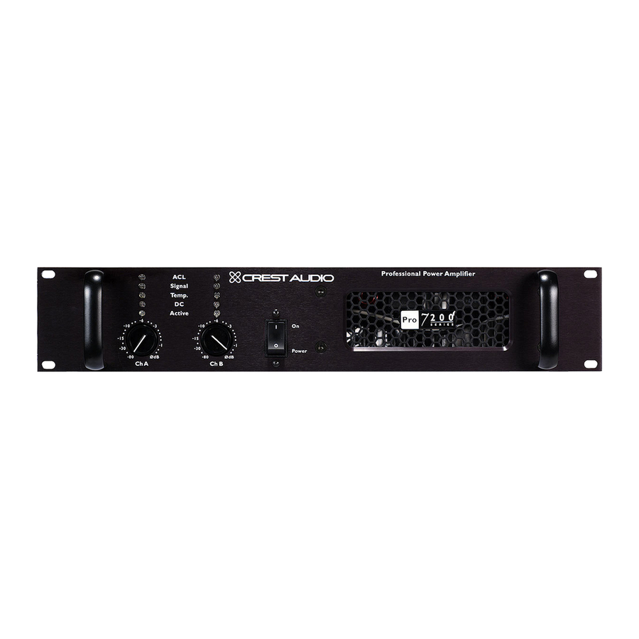
Page 12: Front Panel
Features Overview Front Panel - Pro 8200 shown 2 3 4 Front Panel Rack Mounting Ears Two front-panel mounting holes are provided on each mounting ear. Input Attenuator Whenever possible, set the attenuator fully clockwise to maintain opti- mum system headroom. The input attenuator controls (one for each channel) are located at the front panel, adjust gain for their respective channels in all modes. -
Page 13: Front Panel
Temp LED The Temp LED lights when a channel’s output relay is open, discon- necting the speaker(s) because of an overheating condition. Once the channel temperature has returned to a safe level, the LED will turn off and the speaker(s) will be reconnected. DC LED The DC LED lights when the channel’s output relay is open, discon- necting the speaker(s) when the amplifier senses a DC voltage or sub-... -
Page 14: Rear Panel
Rear Panel Rear Panel Input Connectors Input signals can be connected to the amp via the Neutrik Combicon connectors, using either a TRS or XLR connector. Input sensitivity is .775v (0 dBv) for full rated output power. See — Input Connections in Chapter 5 for more information. -
Page 15: Rear Panel
Air enters through the rear and exits through the front grille. Be sure to allow adequate air flow from the rear of the rack in which the amp is mounted. Binding Post Output Connectors Speakers can be connected via the high current binding posts. One pair of posts is provided (Red- hot, Black- ground) for each channel. -
Page 17: Bridged
Choosing the appropriate mode Switching between operation modes Special considerations when using bridged mode Operation Modes Stereo Parallel Bridged p. 13... -
Page 18: Stereo
Operation Modes Mode Selection The rear panel Mode Select Switch determines whether the amplifier is in stereo, parallel or bridged mono mode. Do not operate the Mode Select Switch with the amplifier on. See the next chapter on Connections for proper wiring in each mode. Stereo For stereo (dual channel) operation, turn the amplifier off and set the Mode Select Switch to the stereo position. -
Page 19: Input
Connecting the amplifier to AC power Proper signal paths: Stereo, Parallel & Bridged Mono Proper wiring schemes for output connectors Connections Power Input Output p. 15... -
Page 20: Output
Connections Power Unless otherwise specified when ordered, Pro 200 Series amplifiers are shipped from the factory set to one of following voltage options: Option 1 US domestic Nominal 120Vac 60Hz for rated power output (safe operating range 100 - 132Vac ) Option 2 Export Nominal 230Vac 50Hz for rated power output (safe operating range... -
Page 21: Bridged Mono Mode
Stereo Mode 5-way binding post connectors Parallel Mode 5-way binding post connectors Bridged Mono Mode 5-way binding post connectors Connections Bridged Mono p. 17... -
Page 22: Output
Connections Stereo Mode Speakon output connectors Parallel Mode Speakon output connectors Bridged Mono Mode Speakon output connectors p. 18 Speaker + to PIN 1 + Speaker - to PIN 1 - Speaker + to PIN 1 + Speaker - to PIN 1 - Bridged Mono Speaker + to PIN 1 + Speaker - to PIN 2 +... -
Page 23: Safety
The owner’s role in amplifier safety Protecting your speakers Description of protection features Safety User Responsibility Speaker Protection Protection Features p. 19... -
Page 24: Speaker Protection
Many loudspeakers can be easily damaged or destroyed by overpowering, especially with the high power available from a bridged amplifier. Always be aware of the speaker’s con- tinuous and peak power capabilities. Crest Audio is not responsible for damage to loud- speakers for any reason. -
Page 25: Protection Features
Protection Features Pro 200 Series amplifiers incorporate several circuits to protect both themselves and loudspeakers. Crest Audio has attempted to make the amplifiers as foolproof as possible by making them immune to short and open circuits, mismatched loads, DC voltage and overheating. -
Page 26: Turn-On/Turn-Off Protection
Safety Turn-On/Turn-Off Protection At power-up,the amplifier stays in the protect mode with outputs disconnected for about six seconds, while the power supplies charge and stabilize.While the output relays are open, the ACL LEDs will light. When the power is turned off, the speaker loads immedi- ately disconnect so that no thumps or pops are heard. -
Page 27: Contact Crest
When to get support Ways to contact Crest Audio Service, Support & Warranty Support Contact Crest Warranty p. 23... -
Page 28: Support
If improperly packed, the unit may be damaged. To obtain service, contact your nearest Crest Audio Service Center, Distributor, Dealer, or any of the worldwide Crest Audio offices. For those with Internet access, please visit the Crest Audio web site. -
Page 29: Specifications
15 k Ohms, balanced >-110dB > -70 dB <15V/µs <0.2% @ 1,900W/ch <0.15% @ 1,300W/ch <0.15% @ 775W/ch 2Ω - 1,875W, 4Ω 1,250W 2Ω - 4,350W, 4Ω 3,050W Power - 5-Way Binding Post & Speakon, - 20A IEC Mains p. 25... -
Page 30: Block Diagram
Block Diagram Channel A Inputs Phoenix Combicon 1/4” Female 3-Pin XLR Channel B Inputs Phoenix Combicon 1/4” Female 3-Pin XLR p. 26 ATTENUATOR OUTPUT STAGE ATTENUATOR MODE SWITCH OUTPUT STAGE A: STEREO B: PARALLEL C: BRIDGE Channel A Outputs 5-Way Neutrik Binding Posts Speakon... -
Page 31: Wire Gauge
Stranded Cable Length Wire Gauge meters 0.75 meters 0.75 meters 0.75 0.75 meters Power Loss 8 Ω load 4 Ω load 2.9% 5.6% 1.74 1.16 0.58 1.16 0.35 0.70 0.22 0.44 4.3% 8.2% 1.45 0.87 1.74 0.55 1.09 0.37 0.73 8.24% 5.5% 10.8... - Page 32 Wire Gauge Stranded Cable Length Wire Gauge feet feet feet feet p. 28 Power Loss 8 Ω load 4 Ω load 0.81% 1.61% 0.51 1.02 0.32 0.64 0.20 0.40 0.128 0.25 1.61% 3.2% 1.02 0.64 1.28 0.40 0.80 0.25 0.51 6.2% 11.9% 1.60...
- Page 33 http://www.crestaudio.com Pro 200 Owner's Manual Version 1.1 11/02...
Need help?
Do you have a question about the PRO7200 and is the answer not in the manual?
Questions and answers