
Related Manuals for Beck 11-439


Summary of Contents for Beck 11-439
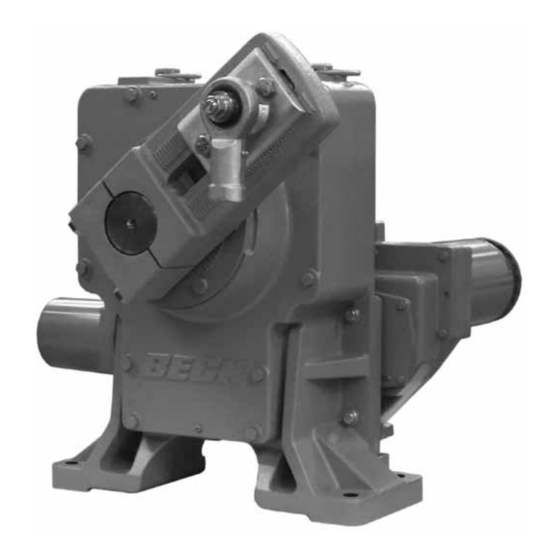
- Page 1 MODEL 11-439 80-1143-03 Rev. 03.1 INSTRUCTION MANUAL E L E C T R I C A C T U A T O R S F O R I N D U S T R I A L P R O C E S S C O N T R O L...
-
Page 2: Table Of Contents
80-1143-03 CONTENTS Product Description ........................... 3 General Specifications ..........................4 Outline Dimension Drawings ........................6 Installation ..............................8 Signal Wiring ............................9 Start-up ..............................10 Operation ..............................12 Digital Control Module (DCM) ........................14 DCM Local Interface ..........................15 Operation ............................15 Calibration ............................ -
Page 3: Product Description
All Beck 11-439 drives are furnished with a crank arm and rod end (see pages 6 and 7 for dimensions). All rod ends furnished by Beck incor- porate bearings to accommodate some lateral mis- alignment. -
Page 4: General Specifications
80-1143-03 PRODUCT DESCRIPTION GENERAL SPECIFICATIONS—ALL MODELS Drive 120 V ac, single-phase, 60 Hz (standard), 50 Hz (optional) Allowable Tolerance: +10% Power 208, 240, 380, 415, 480 & 575 V ac, 50 or 60 Hz (optional) - 15% Max. Current (Amps) by Supply Voltage (V ac) Voltage Model Power (W) - Page 5 80-1143-03 GENERAL SPECIFICATIONS—ALL MODELS (cont’d) Overtorque Protection The DCM-2 shuts off power to the motor if the measured output torque (Optional) of the drive exceeds 150% (adjustable from 70% to 150%) of the drive rating (feature can be enabled/disabled). Alarm Annunciation 120 V, 80 mA max.
-
Page 6: Outline Dimension Drawings
17 13/32 12 7/8 11 9/16 1 19/32 24 39/64 11 7/8 ±3/8 Allow 4" For Removal Front View Side View RECOMMENDED BOLT TORQUES BECK MODEL 11-439 OUTPUT MAXIMUM SIZE TORQUE GEAR REDUCTION UNIT (in.) (lb-ft) SHAFT OVERHUNG TORQUE TIMING WT DIA. - Page 7 80-1143-03 ORIENTATION B 18 15/16 1" N.P.T. Conduit Allow 10" Min. 10 1/8 8 13/16 Power Connection For Access 4 21/32 14 3/8 Cover, Terminal Block 3 1/2 3 1/2 External Wiring 2 63/64 1/2" N.P.T. Conduit Signal Connection 2 3/16 28 13/32 21 3/4 24 1/8...
-
Page 8: Installation
Do a removable wooden pedestal with four 3/4” hex not stack 11-439 crates on top of one another. head bolts. These bolts are not to be used for Stored drives should be checked periodically to mounting the drive to its final mounting platform. -
Page 9: Signal Wiring
Refer to the wiring diagram furnished with your Beck drive for proper AC power and signal con- nections. It is advisable to provide normal short Typical Wiring Connections circuit protection on the AC power line. -
Page 10: Start-Up
4. The radius of the Beck crank arm must be cal- on the Beck drive rather than adjusting the culated so that it will move the damper lever connecting link length. - Page 11 Beck Sales Engineer. Additional Linkage trol signal. If it does not, first check for proper information can be found in the Beck Drive Spec- wiring connections and verify control signal at the ification Guide (DSG).
-
Page 12: Operation
Two over-travel limit switches and up to four the 11-439. In this way, the output torque of the optional auxiliary switches are provided on Beck 11-439 is increased by a factor of 3. - Page 13 80-1143-03 LOSS OF DEMAND INPUT disabled using the HART (see page 48) or Serial interface (see page 71). Torque alarm levels may SIGNAL (L.O.S.) be adjusted using the HART or Serial interfaces. When the Demand input signal drops to Alarm indication is available at terminal E. approximately –5%, the DCM considers the Demand input signal to be invalid.
-
Page 14: Digital Control Module (Dcm)
(see page 56). The DCM modulates the drive output shaft in The DCM permits two or more Beck drives to response to an analog Demand input signal and is be operated by a single signal source. See pages designed to operate continuously in temperatures 21 and 48 for details on split range operation. -
Page 15: Dcm Local Interface
CALIBRATE POSITION SET POS TRQ/THRUST 100% STALL NOTE: Beck drives are shipped from the fac- SET POS tory set up and calibrated to customer spec- TEMP F ifications placed at the time of order and are ready for installation. FB OPEN... - Page 16 80-1143-03 DCM LOCAL INTERFACE Operation Status Indication LEDs Pushbutton Controls When the “STAT” LED is lit, the applicable status The five pushbuttons (pictured below) on the indication LED(s) (pictured below) will light to reveal DCM customer interface panel are used for cali- the condition(s) as described below.
-
Page 17: Calibration
18. CALIBRATION PRIORITY Model 11-439 drives are equipped with fixed, non-adjustable, built-in mechanical stops. All output shaft rotation must occur within these stops, which are approximately 108° apart. -
Page 18: Switches
80-1143-03 DCM LOCAL INTERFACE Calibration - Switches SWITCH ADJUSTMENTS NOTE: Your Beck drive was shipped from the factory ready for installation; no electri cal Control drives are shipped with over-travel adjustments are required before placing it in limit switches factory-set for 101° of travel operation. - Page 19 80-1143-03 Setting Auxiliary Switches 4. Turn the Handswitch to the “STOP” position. 5. Disconnect power from the drive. Standard switch settings for drives with 2 or 4 auxiliary switches are shown on the diagram on 6. Turn the Handswitch to the "AUTO" position. page 18.
-
Page 20: Demand
80-1143-03 DCM LOCAL INTERFACE Calibration - Demand DEMAND CALIBRATION Procedure DCM boards are designed to accept a 4–20 mA 1. Remove the DCM cover (1/2” bolt heads). (or 1–5 V dc) analog demand signal. Narrower 2. Ensure the Handswitch is in the “STOP” spans within this range can also be accommodated position. - Page 21 Square Function NOTE: Ensure that the L.O.S. (Loss of Demand Beck drives can be set up to position the output input signal) settings of the drives are appro- shaft proportionally to the square of the Demand priate for the configuration. See page 13 for input signal (see table below).
-
Page 22: Position
HART (see page 44) or Serial (see tioning during this procedure. page 60) interface. The illustration below represents a Beck drive 4. Press and hold the “CALIBRATE” pushbutton with linkage requiring an 80° full stroke rotation. on the DCM customer interface panel, then (Please note that the crank arm may be adjusted press the “SET POS 0%”... -
Page 23: Direction Change
80-1143-03 DCM LOCAL INTERFACE Calibration - Direction Change DIRECTION OF OUTPUT SHAFT Changing the direction of output shaft rotation is easily accomplished using the DCM customer ROTATION (CW vs. CCW) interface panel (see page 16 for location of push- Direction of output shaft rotation is determined button controls) or the HART or Serial interface. -
Page 24: Troubleshooting
80-1143-03 DCM LOCAL INTERFACE Troubleshooting START Connect proper Is AC voltage at power Does motor Is there a jumper Does drive terminals B & C appear to from terminal A work properly between 102 & energize? to terminal C? 132 V ac? Does drive work with Handswitch? Does drive run... - Page 25 80-1143-03 Note: Choose the side of the slash Move Handswitch Does the voltage Does voltage from corresponding with the to CW/CCW per across terminals CW/CCW switch direction of travel in which direction drive does B–U/B–V = line green/red to term. the drive is not working;...
-
Page 26: Dcm Hart ® Interface
80-1143-03 DCM HART INTERFACE ® Communication BECK-MK2 HART COMMUNICATOR MENUS FOR THE DCM-2 Online (1) Functions Setup Checklist Review (3) 1 Functions 1 Setup Checklist 1 Drive S/N* 2 Position 45.4% 2 Device Information 2 Drive Dir* CW Incr 3 Demand 45.4%... - Page 27 80-1143-03 275/375 HANDHELD COMMUNICATOR WIRING CONNECTIONS CONTROL FIELD ROOM FIELD JUNCTION BOX CONTROLLER DEMAND OUTPUT TO DRIVE MARSHALLING CABINET TERMINATION DEMAND SIGNAL TO DRIVE WIRING (TERMINAL AA& BB) ACCEPTABLE COMMUNICATOR CONNECTION POINTS POLARITY IMPORTANT A 250 ohm load resistor may be required for proper HART communication when the DCM has been modified for...
- Page 28 If the drive is multidropped with other all engineering units are correctly displayed, devices on a single HART network, the first the user must load the BECK-MK2 device ® display screen will list all devices and require a description to the communicator. See page selection before the “Online”...
- Page 29 80-1143-03 MENU DESCRIPTIONS installed. It normally is set at the factory if the board is installed in a drive. The user can edit (See Figure 1, Page 26) the field if desired. 5. Drive S/N - This entry displays the serial Online Menu number of the drive in which the DCM board (Block 1)
- Page 30 80-1143-03 DCM HART INTERFACE ® Communication Configuration Menu 6. StallProt - This entry is set as either “Enabled” or “Disabled". It is used to remove motor (Block 3C) power if "Stall time" is reached. The Configuration menu serves as the 7.
- Page 31 80-1143-03 Demand Setup Submenu Feedback Setup Submenu (Block 4D) (Block 4E) This menu is where all the Demand input This menu is where all the Feedback signal signal related drive parameters are set. The eight related drive parameters are set. The four parameter entries are as follows: parameter entries are as follows: 1.
- Page 32 80-1143-03 DCM HART INTERFACE ® Communication Statistics Menu Manual Operation Menu (Block 3D) (Block 3E) This menu is where all the drive’s stored This menu is used to allow manual drive operating statistics are available. There are eight operation with the HART communicator.
- Page 33 (see This menu provides access to six submenus Demand Setup menu)" displaying various drive status settings: LED TRQ_THRUST_OVERRANGE <Inactive on model 11-439> Status, Operating Status, Switch Status, Local STALL "Stall condition has been detected (see General Setup Cntrl Status, CW Inhibitors, and CCW Inhibitors.
- Page 34 "ON indicates that the DCM is initializing" Stall "ON indicates a Stall condition" CW Torque Submenu OverTrq/Thr <Inactive on model 11-439> Switch Block "ON indicates that the Handswitch, (Block 4J) Override, or Limit Switch is inhibiting movement" This menu displays the torque applied over Bad Pos Sig "ON indicates that the Position signal...
- Page 35 80-1143-03 RealTimeClock Submenu (Block 4M) This menu allows the date and time to be set. The settings are as follows: 1. RTC Day - Numerical entry sets the day of the month. 2. RTC Month - Numerical entry sets the month.
-
Page 36: Configuration And Setup
Carefully follow on-screen warnings and parameters and commands. If unfamiliar with messages when proceeding; changing this the HART communicator and Beck drives, ® parameter will cause the drive to reposition. please review the Communications section This can adversely affect the process and before proceeding. - Page 37 80-1143-03 WARNING WARNING Carefully follow on-screen warnings and Carefully follow on-screen warnings and messages when proceeding; changing this messages when proceeding; changing this parameter will cause the drive to reposition. parameter will cause the drive to reposition. This can adversely affect the process and This can adversely affect the process and cause potentially dangerous conditions.
- Page 38 DEMAND SIGNAL LOSS OF DEMAND INPUT CHARACTERIZATION SIGNAL The Beck DCM is designed to receive a The DCM board has the capability of 4–20 mA (1–5 V dc) input Demand signal and determining when the Demand input signal to the...
- Page 39 80-1143-03 drive is lost, and then responding in the method display to the “Demand Setup” main menu. most appropriate for the application. There are STEP 6 - At the bottom of the “Demand Setup” three setup parameters that must be configured menu, the F2 function key should now be defined in order to define this capability: “LOS Mode”, as the SEND key.
-
Page 40: Calibration
80-1143-03 DCM HART INTERFACE ® Configuration and Setup Enabling Torque Functions Enabling Over-torque Protection STEP 1 - From the HART communicator ® “Online” menu, move to the “Torque Setup” menu STEP 1 - From the HART communicator ® and select the “Trq/Thrust” parameter. This is “Online”... - Page 41 CALIBRATION PRIORITY Model 11-439 drives are equipped with fixed, non-adjustable, built-in mechanical stops. All out- COUNTERCLOCKWISE put shaft rotation must occur within these stops, which are approximately 108°...
-
Page 42: Switches
INTERFACE ® Calibration - Switches SWITCH ADJUSTMENTS NOTE: Your Beck drive was shipped from the factory ready for installation; no electri- Control drives are shipped with over-travel cal adjustments are required before placing limit switches factory-set for 101° of travel it in operation. - Page 43 80-1143-03 Setting Auxiliary Switches 4. Turn the Handswitch to the “STOP” position. 5. Disconnect power from the drive. Standard switch settings for drives with 2 or 4 auxiliary switches are shown on the diagram on 6. Turn the Handswitch to the "AUTO" position. page 42.
-
Page 44: Position
DCM to accept the CPS position signal and interpret the appropriate 0–100% range. All Beck drives are shipped completely set and calibrated to the customer specifications and are ready for installation. Normally, no adjustments are necessary. - Page 45 80-1143-03 Short-stroke Operation (Reducing Full Travel) Typically, it is best to use the full 100% travel of the drive in response to the 0–100% Demand input signal. In certain applications, as a last resort, it may become necessary to reduce the full travel of the drive.
-
Page 46: Feedback
80-1143-03 DCM HART INTERFACE ® Calibration - Feedback FEEDBACK SIGNAL CALIBRATION DCM boards have the capability of providing a 4–20 mA output signal so that the drive’s true output shaft travel can be monitored remotely. The signal comes calibrated from the factory to provide a precise 4–20 mA signal corresponding to 0–100% drive travel. -
Page 47: Demand
80-1143-03 DCM HART INTERFACE ® Calibration - Demand DEMAND SIGNAL CALIBRATION DCM boards are designed to accept a 4–20 mA (or 1–5 V dc) analog Demand signal. Narrower spans within this range can also be accommodated for split range operation (see explanation following). -
Page 48: Torque Measurement
DCM-2 boards have the capability of a single process. Often, this type of control measuring the drive output torque and providing strategy requires that two to four Beck drives several torque-related features. The torque each respond to different portions of one 4–20 measurement is calibrated to the drive’s rated... -
Page 49: Maintenance
The Beck specific messages below provide more descriptive information. “The Demand Signal is outside of the This is a Beck-specific message that can appear after the HART ® intended limits (see Demand Setup defined message above. It specifically pinpoints the Demand input signal to the DCM as the problem source, and indicates that menu)”... - Page 50 The Demand Signal has exceeded its measurable limits and has entered saturation. The value reported for Demand does not reflect the actual value. This is a Beck specific alarm message that alerts the user that "Loop Current Detected while under HART/FF Control"...
- Page 51 Miscellaneous Messages Message Description This is a Beck-specific alarm message that alerts the user that “The Feedback Signal is enabled but the external position feedback signal is installed and enabled, but loop is open” not wired to an external load. If the signal is wired to an external...
-
Page 52: Troubleshooting
80-1143-03 DCM HART INTERFACE ® Maintenance - Troubleshooting ELECTRO / MECHANICAL -- CHART 1 DOES DRIVE WORK PROPERLY START WITH THE HANDSWITCH? IS PROPER AC CONNECT POWER VOLTAGE PROPER CONNECTED POWER ACROSS TERMI- NAL C+ AND B-? IS JUMPER FROM INSTALL TERMINAL A TO C JUMPER... - Page 53 80-1143-03 IS SUPPLY VOLT- AGE ACROSS APPLY TERMINAL C & B CORRECT BETWEEN POWER 102 & 132 V AC? PLACE HAND- SWITCH IN AUTO & MODULATE CONTROL SIGNAL TO DRIVE GO TO DOES DRIVE RUN CHART 2, AT ALL IN AUTO? PG.
- Page 54 80-1143-03 DCM HART INTERFACE ® Maintenance - Troubleshooting ELECTRONICS DIAGNOSTICS -- CHART 2 CONNECT CONNECT ARE ANY HART HART COMMUNI- ARE ANY HART HART COMMUNI- ERROR MESSAGES CATOR & ESTABLISH ERROR MESSAGES CATOR & ESTABLISH DISPLAYED ON THE COMMUNICATIONS DISPLAYED ON THE COMMUNICATIONS COMMUNICATOR? COMMUNICATOR?
- Page 55 80-1143-03 NOTE: ADDITIONAL ERROR MESSAGES AND WARNINGS MAY BE DISPLAYED NOTE: ADDITIONAL ERROR MESSAGES AND WARNINGS MAY BE DISPLAYED ON THE HART COMMUNICATOR. THOSE NOT MENTIONED HERE ON THE HART COMMUNICATOR. THOSE NOT MENTIONED HERE ARE EITHER REDUNDANT OR NOT RELATED TO ERRORS THAT PREVENT ARE EITHER REDUNDANT OR NOT RELATED TO ERRORS THAT PREVENT REVIEW THE REVIEW THE...
-
Page 56: Dcm Serial Interface
Once the computer has been connected to the ® DCM, access HyperTerminal by clicking first on The Beck Digital Control Module (DCM) is "Start", then "Programs", then "Accessories", then equipped with a serial interface which allows for "Communications", then "HyperTerminal". -
Page 57: Commands
80-1143-03 DCM SERIAL INTERFACE Commands COMMANDS AND ARGUMENTS SERIAL COMMANDS Commands can be used for a variety of functions The following is a list of serial commands including changing the operating configuration of available through the RS-232 interface. Error the drive, verifying operation settings, calibration codes associated with these commands are listed and accessing diagnostic information. - Page 58 Sets and/or displays the DCM HART n = "1" (ESR-D); device type. n = "10" (DCM); or n = "239" (BECK-MK2) Demand Signal Commands Argument n and Information Command Description n = the Demand signal as a...
- Page 59 80-1143-03 Command Description Argument n and Information dem100pctma n Sets the Demand signal value that n = the Demand signal as a corresponds to 100% drive position. decimal in milliamps. The minimum acceptable value is the Demand at 0% plus 4.00 mA. For example, if the 0% Demand signal is 4.00 mA, then the 100% Demand signal must be 8.00 mA or greater.
- Page 60 80-1143-03 DCM SERIAL INTERFACE Commands Note: For specific information on the following functions, see the HART interface section of the manual. Position and Feedback Signal Commands Command Description Argument n and Information travel n Sets and/or displays the value that n = the desired length of travel in represents 100% travel.
- Page 61 80-1143-03 Torque Sensing Commands (con't) Command Description Argument n and Information torqconst n Assigns the count value to be n = the torque span value in counts. associated with the torque span. This This number is determined during number is unique to each drive. manufacture and is noted on a tag affixed to the drive body within the electronics compartment.
-
Page 62: Command Error Codes
80-1143-03 DCM SERIAL INTERFACE Command Error Codes Command Error Codes When an error is encountered using the serial commands, an "ERROR XX" message is returned. The table below provides a description of the error codes ("XX"). Code Description Information Invalid selection Displayed when an unknown command has been entered. -
Page 63: Maintenance
GEAR INSPECTION this time to extend life. PLUG CAUTION Before removing the 11-439 from the gear re- duction unit, block the crank arm to prevent the crank arm and the gear train from moving when the 11-439 is removed. Remove the assembly gear module. Remove the gears from their shafts and clean them thor- oughly, removing all old lubrication. -
Page 64: Component Replacement
MAINTENANCE COMPONENT REPLACEMENT MOTOR This section covers replacement of many components of the 11-439 drive. Note that some The control motor is not field-repairable. components are not field repairable. Dis assembly of the motor will result in a loss of... - Page 65 80-1143-03 OVER-TRAVEL LIMIT AND SELF-LOCKING MECHANISM AUxILIARY SWITCHES (SLM) In normal service, the SLM will last for many CAUTION years. Accelerated wear is possible, however, in Do not replace switches until the drive is any drive operating near its rated torque and with disconnected from line voltage and auxiliary a frequency of operation greater than one per switches are disconnected from external...
- Page 66 80-1143-03 MAINTENANCE COMPONENT REPLACEMENT HANDSWITCH If applicable, disconnect the torque sensing wires from the bottom of the customer interface CAUTION panel by gently pulling on the connector. Loosen Before replacing the Handswitch, ensure the four captive screws holding the board to its that the drive is disconnected from the line mounting pads.
- Page 67 80-1143-03 To remove the CPS-2: 1. Run the control drive to its midpoint of travel with the local Handswitch. (If the standard rotation of 100° has been reduced to 80°, the midpoint of travel is 40°.) 2. Disconnect 120 V ac power to the drive. Re- move the terminal, DCM compartment and control end covers (1/2"...
-
Page 68: Appendix
(e.g., 11-439-031891-01-02) given on the that service of your Beck control drive is required. nameplate to allow the factory to verify the part The types of parts are listed in Table 1, below. -
Page 69: Components
Control motor, see Table 2, page 68, for a Gasket, body complete list of part numbers Gasket, change gear plate Handwheel, 6 1/2" O.D. Gasket, control end cover Control end cover To ensure exact replacement parts, include all nameplate data of the Beck drive with the order. -
Page 70: Index
80-1143-03 INDEX Application reviews .......... 71 Installation, mechanical ........8 Beck linkage kits ...........3, 11 Linkage requirements ........10 Components ............ 69 Link-Assist™ ............ 10 Component replacement ......64–67 Loss of Demand input signal ......13 Contactless Position Sensor ......13 Maintenance, routine ........ -
Page 71: Services
1) the repair or replacement, without charge, at Beck’s factory, of any defective equipment covered by this warranty, or 2) at Beck’s option, a full refund of the purchase price. In no event will Beck’s liability exceed the contract price for the goods claimed to be defective. - Page 72 HAROLD BECK & SONS, INC. 11 TERRY DRIVE NEWTOWN, PENNSYLVANIA 18940 USA PHONE: 215-968-4600 FAX: 215-860-6383 www.haroldbeck.com 3/11...
Need help?
Do you have a question about the 11-439 and is the answer not in the manual?
Questions and answers