Table of Contents
Advertisement
Quick Links
1. Introduction
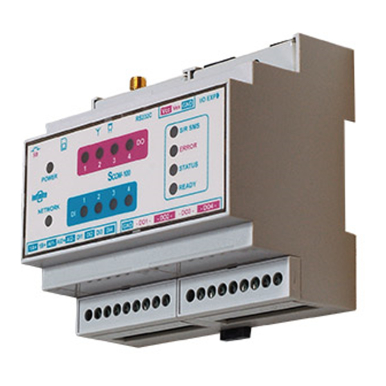
SCOM-100 is a controller unit for alarm annunciation and remote control using SMS.
The main unit incorporates a Quad Band (850/900/1800/1900MHz) GSM modem, 2
analog inputs, 4 digital inputs, 4 power relay outputs (250V/10A) and a serial RS-232
port. Front panel LED indicators monitor control and digital I/O states.
This step by step troubleshooting guide intends to to provide a general idea of
SCOM's SMS handling and troubleshooting, based on a verification method, quickly
and easily.
What you need:
•
An SCOM100.
•
An appropriate power supply to power the unit. Minimum 12VDC, 0.8A
•
A GSM antenna attached to the SCOM100 device.
•
A SIM card capable of seding and receiving SMS messages
Since SCOM100 relies on external factors to provide a functional environment such
us the SIM card, the GSM network coverage and quality, this document will try to
illustrate using simple flowcharts all the possible causes.
2. Power issues
Please follow the SCOM100 device manual to wire an appropriate power supply to
power the unit.
For an
SCOM100-12 a 12VDC/0.8A is needed,
for an SCOM100-24 a 24VDC/1A is needed,
After power up the SCOM100 unit will perform a test procedure. Front panel LEDs
conditions indicating a normal operation should be as follows.
SCOM100
Remote control and alarming
SCOM100: Troubleshooting
Vers. 1.0-1.1.5 – October 2012
Power LED: ON
Network LED:blinking
Status LED: ON
Ready LED: ON
Advertisement
Table of Contents

Related Manuals for Infinite SCOM100

Summary of Contents for Infinite SCOM100
- Page 1 For an SCOM100-12 a 12VDC/0.8A is needed, for an SCOM100-24 a 24VDC/1A is needed, After power up the SCOM100 unit will perform a test procedure. Front panel LEDs conditions indicating a normal operation should be as follows. Power LED: ON...
- Page 2 UPS the AC mains might not be connected or there might be blown fuse. If the device is powered by a power supply connected to the AC mains there might be a blown fuse or a mains failure. SCOM100: Troubleshooting...
- Page 3 SCOM100 Remote control and alarming 2.2 GSM Network operation verification After power up the SCOM100 unit will perform a test procedure. Front panel LEDs conditions indicating a normal operation should be as follows. Power LED: ON Network LED:blinking Status LED: ON...
- Page 4 2. STATUS LED will switch on indicating the RUN (Control) mode. 3. NETWORK LED will be blinking to state successful connection to the GSM provider’s network. The device is now ready to send alarms and information via SMS and and also receive SMS commands. SCOM100: Troubleshooting...
- Page 5 SMS to an SCOM if the operator has a close look at the device, he will notice that S/R LED will blink for 2 seconds when the SMS is received. Similarly when the device sends an SMS the S/R LED will also blink for 2 seconds. SCOM100: Troubleshooting...
- Page 6 SIM card error Modem error Missing I/O expansion module Excessive EM noise or hardware error • Turns on during operation Modem error Excessive EM noise or hardware error STATUS ON: RUN (Control) state Blink: MONITOR state OFF: STOP state SCOM100: Troubleshooting...
- Page 7 The unit does not The device is in STOP mode. send an alarm SMS The respective input is not activated for after a digital input alarming. Activate the input by sending the state changes. proper configuration command (See Manual chapter 4.3). SCOM100: Troubleshooting...
- Page 8 Set the correct analog channel measurement command seem not parameters (see Manual 4.5.1). to be correct. Alarm SMS of an Set a higher alarm delay or a deadband value analog input come for the analog inputs (see Manual 4.5.4) too frequently. SCOM100: Troubleshooting...
Need help?
Do you have a question about the SCOM100 and is the answer not in the manual?
Questions and answers