Advertisement
Quick Links
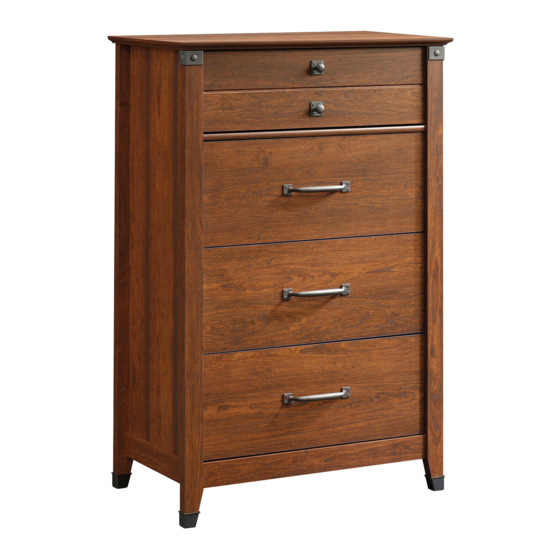
415117
4-Drawer Chest
Carson Forge Collection
PLEASE CONTACT US
BEFORE RETURNING
YOUR UNIT TO THE STORE
1-800-523-3987
www.sauder.com
NOTE: THIS INSTRUCTION BOOKLET CONTAINS
IMPORTANT SAFETY INFORMATION.
PLEASE READ AND KEEP FOR FUTURE REFERENCE.
English .................... Page 1-22
Français ...............Pages 23-25
Made in the USA
Espanol .............Páginas 26-28
Archbold, OH
Lot #: 355966
Date Purchased: ____________________
10 / 11 / 13
Advertisement

Related Manuals for Sauder Carson Forge 415117


Summary of Contents for Sauder Carson Forge 415117
- Page 1 PLEASE READ AND KEEP FOR FUTURE REFERENCE. BEFORE RETURNING English ....Page 1-22 YOUR UNIT TO THE STORE Français ....Pages 23-25 Made in the USA 1-800-523-3987 Espanol .....Páginas 26-28 Archbold, OH www.sauder.com Lot #: 355966 10 / 11 / 13 Date Purchased: ____________________...
- Page 2 LEFT FRONT LEG REAR LEG LARGE DRAWER FRONT DRAWER FRONT BOTTOM MOLDING END MOLDING BACK RIGHT DRAWER SIDE LEFT DRAWER SIDE LARGE RIGHT DRAWER SIDE LARGE LEFT DRAWER SIDE DRAWER BACK D171 LARGE DRAWER BACK D945 DRAWER BOTTOM Page 2 www.sauder.com/services 415117...
-
Page 3: Part Identification
SLIDE CAM - 8 8E CORNER ACCENT - 2 40CD DRAWER LEFT - 4 FOOT - 4 TACK GLIDE - 4 HIDDEN CAM - 18 CAM DOWEL - 12 CAM SCREW - 6 SAFETY BRACKET - 1 415117 www.sauder.com/services Page 3... - Page 4 BLACK 1-9/16" FLAT HEAD SCREW - 20 BLACK 9/16" FLAT HEAD SCREW - 4 SILVER 1/2" MACHINE SCREW - 6 GOLD 1" MACHINE SCREW - 2 Screws are shown actual size. You may receive extra hardware with your unit. Page 4 www.sauder.com/services 415117...
- Page 5 Look for this icon. It means a video assembly tip is available at: www.sauder.com/services/tips Do not tighten the HIDDEN CAMS in this step. Arrow Do not insert CAM DOWELS into these edges. Arrow Arrow (12 used) (18 used) Arrow Arrow Insert the metal end of the CAM DOWEL into the HIDDEN CAM.
- Page 6 (2 used in this step) (6 used) Angled edge Turn six CAM SCREWS (8F) into the FRONT LEGS (G and H). Fasten two CORNER ACCENTS (8E) to the FRONT LEGS (G and H). Use two SILVER 5/8" MACHINE SCREWS (15S). Page 6 www.sauder.com/services 415117...
- Page 7 Turn four BLACK 9/16" FLAT HEAD SCREWS (32S) into the ENDS (A and B) until the shoulder of the SCREWS rests on the surface of the ENDS. Slide the MOLDINGS (M) onto the ENDS (A and B). Line up the groove in the MOLDINGS over the head of the SCREWS in the ENDS. 415117 www.sauder.com/services Page 7...
- Page 8 Angled edge Fasten the FRONT LEGS (G and H) to the ENDS (A and B). Tighten six HIDDEN CAMS. Insert four SAFETY STOPS (29G) into the holes shown in the RIGHT END (A). Page 8 www.sauder.com/services 415117...
- Page 9 INTERLOCK TRACK edges have been snapped into the CABINET ACTUATORS as shown in diagram 3. Diagram 5. Remove the INTERLOCK TRACK assembly from Diagram 4 and flip it over before inserting the INTERLOCK TRACK (21G) with CABINET ACTUATORS (29G) into the groove in the RIGHT END (A). 415117 www.sauder.com/services Page 9...
- Page 10 Remove the drawers to re-adjust the INTERLOCK TRACK assembly. Fasten four CABINET RIGHTS (40CA) and four CABINET LEFTS (40CB) to the ENDS (A and B). Use sixteen GOLD 5/16" FLAT HEAD SCREWS (3S) through holes #1 and #3. Page 10 www.sauder.com/services 415117...
- Page 11 Tighten Arrow Risk of damage or injury. Hidden Cams must be completely Arrow Maximum tightened. Hidden 210 degrees Cams that are not completely tightened Minimum may loosen, and parts 190 degrees may separate. To completely tighten: 415117 www.sauder.com/services Page 11...
- Page 12 Arrow 210 degrees Minimum 190 degrees Fasten the BOTTOM (D) to the LEFT END (B). Tighten two HIDDEN CAMS. Slide the BOTTOM MOLDING (L) onto the notched edge of the BOTTOM (D). *U.S. Patent No. 5,499,886 Page 12 www.sauder.com/services 415117...
- Page 13 Fasten the RIGHT END (A) to the TOP (C) and BOTTOM (D). Tighten four HIDDEN CAMS. NOTE: Be sure the METAL PINS (1R) in the end of the DUST RAIL (E) insert into the holes in the RIGHT END (A). NOTE: You may need help in this step. 415117 www.sauder.com/services Page 13...
- Page 14 Carefully turn your unit over onto its front edges. Unfold the BACK (N) and lay it over your unit. Make equal margins along all four edges of the BACK (N). Push on opposite corners of your unit if needed to make it “square”. Fasten the BACK (N) to your unit using the NAILS (1N). Page 14 www.sauder.com/services 415117...
- Page 15 Push four FEET (10E) onto the LEGS (G, H, and I). With a hammer, gently tap four TACK GLIDES (12E) through the holes of the FEET (10E). 415117 www.sauder.com/services Page 15...
- Page 16 DRAWER SIDES (D30 and D31) and DRAWER BRACE (F). Fasten the DRAWER BRACE (F) to the LARGE DRAWER Use five BLACK 1-9/16" FLAT HEAD SCREWS. Repeat this FRONT (J). Tighten one HIDDEN CAM. step for the remaining drawers. Page 16 www.sauder.com/services 415117...
- Page 17 Fasten a DRAWER LEFT (40CD) to the LARGE LEFT DRAWER SIDE (D31). Use two GOLD 5/16" FLAT HEAD SCREWS (3S) through holes #2 and #4. NOTE: The screw head in the CAM must be visible through the slotted hole in the SLIDE. 415117 www.sauder.com/services Page 17...
- Page 18 Now, fasten this DRAWER RIGHT (40CC) to the LARGE RIGHT DRAWER SIDE (D30). Use two GOLD 5/16” FLAT HEAD SCREWS (3S) through holes #2 and #4. NOTE: The screw head in the CAM must be visible through the slotted hole in the SLIDE. Repeat steps 13 and 14 for the other drawers. Page 18 www.sauder.com/services 415117...
- Page 19 Fasten two KNOBS (52K) to the DRAWER FRONT (K). Use two GOLD 1" MACHINE SCREWS (50S). Fasten a PULL (53K) to the LARGE DRAWER FRONT (J). Use two SILVER 1/2" MACHINE SCREWS (38S). Repeat this step for the remaining LARGE DRAWER FRONTS (J). 415117 www.sauder.com/services Page 19...
- Page 20 We recommend using the SAFETY BRACKET (1G) for added stability. Use a BLACK 9/16" LARGE HEAD SCREW (1S) into the top of the unit and a BLACK 1-7/8" PAN HEAD SCREW (16S) into a stud in your wall. Page 20 www.sauder.com/services 415117...
- Page 21 When the drawer is closed, it will hide the label. Peel off the backing and apply the label as shown in the diagram. NOTE: This is a permanent label intended to last for the life of the product. Once applied, do not try to remove it. 415117 www.sauder.com/services Page 21...
- Page 22 Tighten the SCREW when finished with adjustments. NOTE: Please read the back pages of the instruction booklet for important safety information. This completes assembly. To clean your unit, dampen a cloth with tap water and wipe. Page 22 www.sauder.com/services 415117...
-
Page 23: Liste De Pièces
CLOU ............40 pour future référence. D171 ARRIÈRE DE GRAND TIROIR ...... 3 GOUPILLE EN MÉTAL ........4 Pour contacter Sauder D945 FOND DE TIROIR .......... 4 en ce qui concerne cet VIS TÊTE LARGE 14 mm NOIRE ....1 élément, faire référence... - Page 24 À l’aide d’un marteau, enfoncer quatre PATINS (12E) à travers les du Schéma 4 et le retourner avant d’insérer le RAIL DE trous des PIEDS (10E). VERROUILLAGE (21G) avec les ACTIONNEURS D'ÉLÉMENT (29G) dans la rainure de l’EXTRÉMITÉ DROITE (A). Page 24 www.sauder.com/services 415117...
- Page 25 VIS À MÉTAUX 25 mm DORÉES (50S). Fixer une POIGNÉE (53K) sur le DEVANT DE GRAND TIROIR (J). Utiliser deux VIS À MÉTAUX 13 mm ARGENT (38S). Répéter cette étape pour les autres DEVANTS DE GRAND TIROIR (J). 415117 www.sauder.com/services Page 25...
-
Page 26: Lista De Partes
D945 FONDO DE CAJÓN ........4 TORNILLO PLATEADO PARA METAL en contacto con de 16 mm ............2 Sauder en cuanto a TORNILLO NEGRO DE CABEZA esta unidad, refi érase REDONDA de 48 mm ........1 al número de lote y TORNILLO NEGRO DE CABEZA al número de modelo... - Page 27 4 y voltéelo antes de insertar el CARRIL DE UNIÓN (21G) con Con un martillo, inserte cuatro TACHUELAS DESLIZANTES (12E) a los ACTUADORES DE GABINETE (29G) entre la ranura en el través de los agujeros de las PATAS (10E). EXTREMO DERECHO (A). 415117 www.sauder.com/services Page 27...
- Page 28 TORNILLOS DORADOS PARA METAL de 25 mm (50S). Fije un TIRADOR (53K) a la CARA DE CAJÓN GRANDE (J). Utilice dos TORNILLOS PLATEADOS PARA METAL de 13 mm (38S). Repita este paso para las otros CARAS DE CAJÓN GRANDE (J). Page 28 www.sauder.com/services 415117...
- Page 29 équipé. • Blessure physique. Le mobilier peut • Ne pas pousser le mobilier, surtout sur la être très lourd. moquette. 415117 www.sauder.com/services Page 29...
- Page 30 • No empuje la unidad, especialmente • Lesión física. El mobiliario puede ser sobre un piso alfombrado. muy pesado. Page 30 www.sauder.com/services 415117...
-
Page 31: Year Limited Warranty
4. La présente garantie ne s’applique qu’aux défauts garantis qui se produisent des composantes de mobilier Sauder. Le mot « défaut », tel qu’il est utilisé sous pour la première fois et qui sont signalés à Sauder dans les limites de ouverture les termes de la présente garantie, comprend les imperfections des pièces qui... - Page 32 Archbold, Ohio, where it all began. Certifi cate of Conformity The Sauder name on the box ensures that 1. This certifi cate applies to the Sauder Woodworking Product identifi ed by this Instruction Book. the item you have purchased is made with 2.
Need help?
Do you have a question about the Carson Forge 415117 and is the answer not in the manual?
Questions and answers