Table of Contents
Advertisement
Quick Links
Advertisement
Table of Contents

Subscribe to Our Youtube Channel
Related Manuals for EchoMaster Pro 19366656


Summary of Contents for EchoMaster Pro 19366656
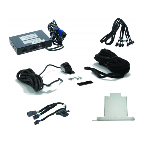
- Page 1 Installation/USER Guide IntelliHaul Integrated Front Camera Assistance Package...
-
Page 2: Prior To Installation
19366656 Integrated Front Camera Assistance Package Prior to Installation Cover all surfaces with tape or plastic protection film to protect against scratching and damage. EchoMaster is in no way responsible for any damage that may incur during installation. This product has been validated in the vehicles listed on the application guide only. -
Page 3: Recommended Tools
19366656 Integrated Front Camera Assistance Package Vehicle Preparation & Protection CAUTION Consult your vehicle owner’s manual to disconnect the battery. Do not disconnect ANY airbag connectors or indicators. Doing so may result in activating a diagnostic code. These codes will require the dealer to perform the reset procedure which may incur a reset fee. -
Page 4: Removing The Radio
19366656 Integrated Front Camera Assistance Package Removing the Radio Using a plastic dash removal tool, remove the trim from around the LCD display. Remove the 4 x 7mm bolts from around the LCD display. Once screws have been removed, pull the unit from the dash. - Page 5 19366656 Integrated Front Camera Assistance Package Remove the glovebox for easier access for running cables. Remove the PINS from the hinges. Recommended Mounting Locations Mount directly under front em- blem (for parking) Mount lower for off road use on the underside of the grille for better viewing when rock crawling or off roading.
- Page 6 19366656 Integrated Front Camera Assistance Package Routing the Camera Extension Harness Route the camera cable along the inside of the grille. Route the camera cable along the hood release cable using the hood release holders to hold the camera cable in place.
- Page 7 19366656 Integrated Front Camera Assistance Package Routing the Camera Extension Harness Inside the vehicle, route the cable under the dash to the appropriate connector on the main camera harness extension in the glove box area. PLEASE NOTE Avoid all moving parts inside the dash as well as under the hood.
-
Page 8: Module Connections
19366656 Integrated Front Camera Assistance Package Module Connections Connect 8-pin power T-harness to module. Next, connect 16-pin main camera extension cable to module. Then, fasten harnesses to the bracket using zip ties through the holes provided. Please select the size of the monitor using dip switch 1 u Up for 8”... - Page 9 19366656 Integrated Front Camera Assistance Package LVDS Connection Locate HMI module in lower portion of radio cavity Disconnect BLUE LVDS connector. Connect loose male LVDS connector into female EchoMaster connector. Connect the male EchoMaster LVDS connector into HMI module. Secure loose wiring with zip ties.
-
Page 10: Wiring Diagram
19366656 Integrated Front Camera Assistance Package Wiring Diagram Illustrations are typical and may not match exact vehicle details For installation assistance visit http://echomaster.com/Intellihaul/ email - gmsupport@echomaster.com (US) - tel - 866-766-2267... - Page 11 USER Guide 19366656 Integrated Front Camera Assistance Package 8” Radio Press and hold the “BACK” button for three seconds to display the IntelliHaul camera view. Press the “BACK” button to return to the factory screen. 4” Radio Press and hold the “HOME” button for three seconds to enter the IntelliHaul camera view.
- Page 12 AGREEMENT: End user agrees to use this product in compliance with the instructions and terms of use above and with all State and Federal laws. EchoMaster provides instructions and safety warnings with respect to this product and disclaims all liability for any use not in conformity with those instructions or other misuse of its product.
Need help?
Do you have a question about the 19366656 and is the answer not in the manual?
Questions and answers