Table of Contents
Advertisement
Advertisement
Table of Contents

Related Manuals for Lenovo Tab P10 Series


Summary of Contents for Lenovo Tab P10 Series
- Page 1 Lenovo Tab P10 Lenovo TB-X705F Lenovo TB-X705L Hardware Maintenance Manual...
- Page 2 First Edition (September 2018) © Copyright Lenovo 2018. All rights reserved. LENOVO products, data, computer software, and services have been developed exclusively at private expense and are sold to governmental entities as commercial items as defined by 48 C.F.R. 2.101 with limited and restricted rights to use, reproduction and disclosure.
-
Page 3: Table Of Contents
1070 Antenna ..........35 1080 LCD module FPC ....... 37 1090 System board........38 1100 Cameras ..........41 Locations............. 42 Lenovo Tab P10 overview......42 Parts list .............. 43 Overall............43 Screws ............45 Ac adapters and USB cable ......45 Label .............. -
Page 4: About This Manual
TB-X705F TB-X705L Use this manual to troubleshoot problems. Note: The illustrations used in this manual are for Lenovo TB-X705F unless otherwise stated. The manual is divided into the following sections: • The common sections provide general information, guidelines, and safety information required for servicing computers. -
Page 5: Safety Information
Safety information Safety information This chapter presents the following safety information that you need to get familiar with before you service a Lenovo computer: • “General safety” on page 2 • “Electrical safety” on page 3 • “Safety inspection guide” on page 5 •... -
Page 6: General Safety
Hardware Maintenance Manual General safety Follow these rules below to ensure general safety: • Observe a good housekeeping in the area where the machines are put during and after the maintenance. • When lifting any heavy object: 1. Make sure that you can stand safely without slipping. 2. -
Page 7: Electrical Safety
Safety information Electrical safety Observe the following rules when working on electrical equipments. Important: Use only approved tools and test equipments. Some hand tools have handles covered with a soft material that does not insulate you when working with live electrical currents. Many customers have rubber floor mats near their machines that contain small conductive fibers to decrease electrostatic discharges. - Page 8 Hardware Maintenance Manual • Always look carefully for possible hazards in your work area. Examples of these hazards are moist floors, nongrounded power extension cables, power surges, and missing safety grounds. • Do not touch live electrical circuits with the reflective surface of a plastic dental mirror.
-
Page 9: Safety Inspection Guide
4. Check for cracked or bulging batteries. 5. Remove the cover. 6. Check for any obvious non-Lenovo alterations. Use good judgment as to the safety of any non-Lenovo alterations. 7. Check inside the unit for any obvious unsafe conditions, such as metal filings, contamination, water or other liquids, or signs of fire or smoke damage. -
Page 10: Handling Devices That Are Sensitive To Electrostatic Discharge
Hardware Maintenance Manual Handling devices that are sensitive to electrostatic discharge Any computer part containing transistors or integrated circuits (ICs) should be considered sensitive to electrostatic discharge (ESD). ESD damage can occur when there is a difference in charge between objects. Protect against ESD damage by equalizing the charge so that the machine, the part, the work mat, and the person handling the part are all at the same charge. -
Page 11: Safety Notices: Multilingual Translations
Safety information Safety notices: multilingual translations The safety notices in this section are provided in English, French, German, Hebrew, Italian, Japanese, and Spanish. Safety notice 1 Before the computer is powered on after FRU replacement, make sure all screws, springs, and other small parts are in place and are not left loose inside the computer. - Page 12 Hardware Maintenance Manual Safety notice 2 DANGER Some standby batteries contain a small amount of nickel and cadmium. Do not disassemble a standby battery, recharge it, throw it into fire or water, or short-circuit it. Dispose of the battery as required by local ordinances or regulations.
- Page 13 Safety information Safety notice 3 DANGER The battery pack contains small amounts of nickel. Do not disassemble it, throw it into fire or water, or short-circuit it. Dispose of the battery pack as required by local ordinances or regulations. Use only the battery in the appropriate parts listing when replacing the battery pack.
- Page 14 Hardware Maintenance Manual Safety notice 4 DANGER The lithium battery can cause a fire, an explosion, or a severe burn. Do not recharge it, remove its polarized connector, disassemble it, heat it above 100°C (212°F), incinerate it, or expose its cell contents to water. Dispose of the battery as required by local ordinances or regulations.
- Page 15 Safety information Safety notice 5 If the LCD breaks and the fluid from inside the LCD gets into your eyes or on your hands, immediately wash the affected areas with water at least for 15 minutes. Seek medical care if any symptoms caused by the fluid are present after washing.
- Page 16 Hardware Maintenance Manual Safety notice 6 DANGER To avoid shock, do not remove the plastic cover that protects the lower part of the inverter card. Afin d’éviter tout risque de choc électrique, ne retirez pas le cache en plastique protégeant la partie inférieure de la carte d’alimentation. Aus Sicherheitsgründen die Kunststoffabdeckung, die den unteren Teil der Spannungswandlerplatine umgibt, nicht entfernen.
- Page 17 Safety information Safety notice 8 DANGER Before removing any FRU, turn off the computer, unplug all power cords from electrical outlets, remove the battery pack, and then disconnect any interconnecting cables. Avant de retirer une unité remplaçable en clientèle, mettez le système hors tension, débranchez tous les cordons d’alimentation des socles de prise de courant, retirez la batterie et déconnectez tous les cordons d’interface.
-
Page 18: Laser Compliance Statement
Hardware Maintenance Manual Laser compliance statement Some models of Lenovo computer are equipped from the factory with an optical storage device such as a CD-ROM drive or a DVD-ROM drive. Such devices are also sold separately as options. If one of these drives is installed, it is certified in the U.S. - Page 19 Safety information A CD-ROM drive, a DVD-ROM drive, or any other storage device installed may contain an embedded Class 3A or Class 3B laser diode. Note the following: DANGER Emits visible and invisible laser radiation when open. Do not stare into the beam, do not view directly with optical instruments, and avoid direct exposure to the beam.
-
Page 20: Important Service Information
To download software fixes, drivers, and BIOS, follow the steps below: 1. Go to http://consumersupport.lenovo.com/. 2. Enter a serial number or select a product or use Lenovo smart downloading. 3. Select the BIOS/Driver/Applications and download. 4. Follow the directions on the screen and install the necessary software. -
Page 21: Important Notice For Replacing A System Board
Important service information Use the following strategy to prevent unnecessary expense for replacing and servicing FRUs: • If you are instructed to replace an FRU, but the replacement does not solve the problem, reinstall the original FRU before you continue. •... -
Page 22: Important Information About Replacing Rohs Compliant Frus
Electronic Equipment Directive (2002/95/EC) is a European Union legal requirement affecting the global electronics industry. RoHS requirements must be implemented on Lenovo products placed on the market after June 2006. Products on the market before June 2006 are not required to have RoHS compliant parts. -
Page 23: General Checkout
General checkout General checkout This chapter presents the following information: • “What to do first” on page 20 Before you go to the checkout, make sure to read the following important notes: Important notes: • Only certified trained personnel can service the computer. •... -
Page 24: What To Do First
Hardware Maintenance Manual What to do first When you do return an FRU, you must include the following information in the parts exchange form or parts return form that you attach to it: 1. Name and phone number of servicer 2. -
Page 25: Lenovo Tab P10
This section presents notices related to removing and replacing parts. Read this section carefully before replacing any FRU. Screw notices Loose screws can cause a reliability problem. In the Lenovo computer, this problem is addressed with special nylon-coated screws that have the following characteristics: •... - Page 26 Hardware Maintenance Manual • Logic card to plastic Turn an additional 180° after the screw head touches the surface of the logic card: more than 180° (Cross-section) • Torque driver If you have a torque screwdriver, refer to the “Torque” column for each step. •...
-
Page 27: Removing And Replacing An Fru
Lenovo Tab P10 Removing and replacing an FRU This section presents exploded figures with the instructions to indicate how to remove and replace the FRU. Make sure to observe the following general rules: 1. Do not attempt to service any computer unless you have been trained and certified. -
Page 28: 1010 Card Tray
Hardware Maintenance Manual 1010 Card tray Figure 1. Removal steps of card tray Insert a pin into the hole of the card tray, and then pull out the card tray. -
Page 29: 1020 Battery Cover
Lenovo Tab P10 1020 Battery cover For access, remove this FRU: • “1010 Card tray” on page 24 Figure 2. Removal steps of battery cover Heat the four sides of the battery cover by hair dryer for about 3 minutes. Then insert a teardown piece, and slide along the sides to release the battery cover. -
Page 30: 1030 Battery Pack
• “1010 Card tray” on page 24 • “1020 Battery cover” on page 25 Figure 3. Removal steps of battery pack Remove the screws . Detach the bracket for battery pack connector Lenovo TB-X705F Lenovo TB-X705L Step Screw (quantity) Color Torque M1.4 ×... - Page 31 Lenovo Tab P10 Figure 3. Removal steps of battery pack (continued) Unplug the battery pack connector . Pull out the tapes . Then remove the battery pack Lenovo TB-X705F Lenovo TB-X705L...
-
Page 32: 1040 Speakers
• “1010 Card tray” on page 24 • “1020 Battery cover” on page 25 • “1030 Battery pack” on page 26 Figure 4. Removal steps of speakers Remove the screws Lenovo TB-X705F Step Screw (quantity) Color Torque M1.4 × 2.5 mm, Phillips head(11) Black Appr. - Page 33 Lenovo Tab P10 Figure 4. Removal steps of speakers (continued) Unplug the bracket for fingerprint module connector Lenovo TB-X705F Lenovo TB-X705L Unplug POGOPIN FPC connector and fingerprint module connector Unplug the speaker connectors by lifting the speakers and releasing the speaker...
- Page 34 Hardware Maintenance Manual Figure 4. Removal steps of speakers (continued) Lenovo TB-X705L Remove the speakers Lenovo TB-X705F Lenovo TB-X705L...
-
Page 35: 1050 Fingerprint Module And Pogopin Fpc
Lenovo Tab P10 1050 Fingerprint module and POGOPIN FPC For access, remove these FRUs in order: • “1010 Card tray” on page 24 • “1020 Battery cover” on page 25 • “1030 Battery pack” on page 26 • “1040 Speakers” on page 28 Figure 5. - Page 36 Hardware Maintenance Manual Figure 5. Removal steps of fingerprint module and POGOPIN FPC (continued) Remove POGOPIN FPC Lenovo TB-X705F Lenovo TB-X705L...
-
Page 37: 1060 Sim Card Slot And Vibrator Module
Lenovo Tab P10 1060 SIM card slot and vibrator module For access, remove these FRUs in order: • “1010 Card tray” on page 24 • “1020 Battery cover” on page 25 • “1030 Battery pack” on page 26 • “1040 Speakers” on page 28 •... - Page 38 Hardware Maintenance Manual Figure 6. Removal steps of SIM card slot and vibrator module (continued) Remove the SIM card slot and vibrator module. Lenovo TB-X705F Lenovo TB-X705L...
-
Page 39: 1070 Antenna
Lenovo Tab P10 1070 Antenna For access, remove these FRUs in order: • “1010 Card tray” on page 24 • “1020 Battery cover” on page 25 • “1030 Battery pack” on page 26 • “1040 Speakers” on page 28 • “1050 Fingerprint module and POGOPIN FPC” on page 31 •... - Page 40 Hardware Maintenance Manual Figure 7. Removal steps of antenna module (continued) Remove the screw and the antenna module Lenovo TB-X705F Lenovo TB-X705L Step Screw (quantity) Color Torque M1.4 × 3.5 mm, Phillips head(1) Silver Appr. 0.6 kgf·cm...
-
Page 41: 1080 Lcd Module Fpc
Lenovo Tab P10 1080 LCD module FPC For access, remove these FRUs in order: • “1010 Card tray” on page 24 • “1020 Battery cover” on page 25 • “1030 Battery pack” on page 26 • “1040 Speakers” on page 28 •... -
Page 42: 1090 System Board
• “1070 Antenna” on page 35 • “1080 LCD module FPC” on page 37 Figure 9. Removal steps of system board Detach the side key connector , and remove the screws Lenovo TB-X705F Step Screw (quantity) Color Torque M1.4 × 2.5 mm, Phillips head(12) Black Appr. - Page 43 Lenovo Tab P10 Figure 9. Removal steps of system board (continued) Lenovo TB-X705L Step Screw (quantity) Color Torque M1.4 × 2.5 mm, Phillips head(8) Black Appr. 0.6 kgf·cm M1.4 × 3.5 mm, Phillips head(3) Silver Appr. 0.6 kgf·cm Detach the audio connector jacket...
- Page 44 Hardware Maintenance Manual Figure 9. Removal steps of system board (continued) Remove the system board Lenovo TB-X705F Lenovo TB-X705L...
-
Page 45: 1100 Cameras
Lenovo Tab P10 1100 Cameras For access, remove these FRUs in order: • “1010 Card tray” on page 24 • “1020 Battery cover” on page 25 • “1030 Battery pack” on page 26 • “1040 Speakers” on page 28 • “1050 Fingerprint module and POGOPIN FPC” on page 31 •... -
Page 46: Locations
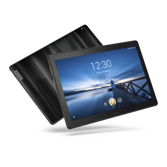
Headset connector Rear camera Flash Volume buttons Power button Smart connector The WLAN version (Lenovo TB-X705F) does not have a Nano-SIM card slot. All pictures and illustrations in this document are for reference only and may differ from the final product. -
Page 47: Parts List
Lenovo Tab P10 Parts list This section presents the following service parts: • “Overall” on page 43 • “Screws” on page 45 • “Ac adapters and USB cable” on page 45 • “Label” on page 45 • “Rubber and mylar” on page 45 Note: •... - Page 48 Hardware Maintenance Manual Table 1. Parts list—Overall FRU no. YD-50250100191LE P100F SIM TRAY BLK S948C38574 YD-50250100190LE P100F SIM TRAY SLV S948C38573 YD-50250100189LE P101F SIM TRAY BLK S948C38572 YD-50250100188LE P101F SIM TRAY SLV S948C38571 TB-X705F TP LCM_BL&*72600100408 CS 5D68C12055 TB-X705F TP LCM_WH&*72600100409 CS 5D68C12056 TB-X705L TP LCM_BL&*72600100411 CS 5D68C12057...
-
Page 49: Screws
S948C38384 YD-44100100069LE Srew M1.4*1.8 S948C38381 Ac adapters and USB cable Table 3. Parts list— Ac adapters and USB cable FRU no. ACCY,AC ADPTR,Golf Lite,5VV,2A,Lenovo ne SA18C30143 ACCY,AC ADPTR,Golf Lite,5VV,2A,Lenovo ne SA18C30144 ACCY,AC ADPTR,Golf Lite,5VV,2A,Lenovo ne SA18C30145 ACCY,AC ADPTR,Golf Lite,5VV,2A,Lenovo ne... -
Page 50: Tape And Poron
Hardware Maintenance Manual Tape and poron Table 7. Parts list— Tape and poron FRU no. YD-56600100316LE P100F SPK BOX EE-TAPE S948C38737 YD-56600100321LE P100F SKEY FPC EE-TAPE S948C38742 YD-56600100317LE P100F CAMERA-F EE-TAPE S948C38738 YD-56600100318LE P100F FINGER EE-TAPE S948C38739 YD-56700100076LE P100F SPK BOX1 EE-TAPE S948C38744 YD-56200100303LE P100F BATTERY PORON S948C38724... -
Page 51: Notices
The result obtained in other operating environments may vary. Lenovo may use or distribute any of the information you supply in any way it believes appropriate without incurring any obligation to you. -
Page 52: Trademarks
Actual results may vary. Users of this document should verify the applicable data for their specific environment. Trademarks The following terms are either registered trademarks or trademarks of Lenovo in the United States and/or other countries: ® Lenovo ®...
Need help?
Do you have a question about the Tab P10 Series and is the answer not in the manual?
Questions and answers