
Subscribe to Our Youtube Channel
Related Manuals for infobit iMatrix H44A

Summary of Contents for infobit iMatrix H44A
- Page 1 4x4 HDMI 2.0 18Gbps Matrix Switcher with Audio User Manual V1.0 Model: iMatrix H44A INFOBIT AV www.infobitav.com info@infobitav.com...
-
Page 2: Table Of Contents
5.3 Connecting to the Switcher................ 7 5.4 Using the Switcher ..................7 6. IR Remote ......................8 7. Using the Bulit-In Web GUI Interface ..............9 8. API control command ..................18 9. Application Example ..................24 INFOBIT AV www.infobitav.com info@infobitav.com... -
Page 3: Introduction
☆ ARC audio return to the coaxial ports output only ☆ Built-in Web GUI for TCP/IP control ☆ Advanced EDID management supported ☆ Four methods of control: Front panel, RS-232, IR remote and TCP/IP ☆ Compact design for easy and flexible installation INFOBIT AV www.infobitav.com info@infobitav.com... -
Page 4: Package Contents
RGB, YCbCr4:4:4,YCbCr4:2:2, YCbCr 4:2:0 Color Depth 8-bit, 10-bit, 12-bit [1080P, 4K30Hz, 4K60Hz (YCbCr 4:2:0)] 8-bit [4K60Hz (YCbCr 4:4:4)] HDMI Audio Formats PCM2.0/5.1/7.1CH, Dolby Digital/Plus/EX, Dolby True HD, DTS, DTS-EX,DTS-96/24, DTS High Res, DTS-HD Master Audio, DSD INFOBIT AV www.infobitav.com info@infobitav.com... - Page 5 1080P60 - Cable Length Feet / Meters Feet / Meters Feet / Meters HDMI IN / OUT 10ft / 3M 30ft / 10M 42ft / 15M The use of “Premium High Speed HDMI” cable is highly recommended. INFOBIT AV www.infobitav.com info@infobitav.com...
-
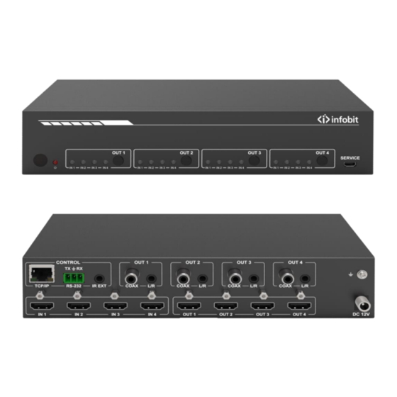
Page 6: Operation Controls And Functions
Function description TCP/IP (RJ45) Control port for TCP/IP control or accessing the built-in Web GUI. RS-232 3-pin pluggable connector for RS-232 control of the Switcher. IR EXT IR eye input for IR control of the Switcher. INFOBIT AV www.infobitav.com info@infobitav.com... -
Page 7: Connecting To The Switcher
5.4.1 Power LED and Standby Mode The Power LED provides the following indications: Color Description The Switcher is active and fully controllable The Switcher is in standby mode, this state can be changed by using API commands or IR INFOBIT AV www.infobitav.com info@infobitav.com... -
Page 8: Ir Remote
Output 1 (Output 2 / 3 / 4) 1/2/3/4 Select the desired input source to Output 1 port output, the corresponding green LED on the front panel illuminates. Switch downscale or bypass mode to the Output 1 port output. INFOBIT AV www.infobitav.com info@infobitav.com... -
Page 9: Using The Bulit-In Web Gui Interface
Status and Video pages are available. To access the Web interface, enter the IP address of the switcher into the address bar of any web brower. The default IP address is 192.168.1.100. INFOBIT AV www.infobitav.com info@infobitav.com... - Page 10 Step 2: Set your PC IP address to the same network segment with Switcher, for instance set PC IP address to 192.168.1.200 and Subnet mask to 255.255.255.0. Step 3: Enter the Switcher’s IP address into your brower on the PC to enter INFOBIT AV www.infobitav.com info@infobitav.com...
- Page 11 Status page will appear. ■ Status page The Status page provides basic information about the product Model name, the installed firmware version and the network setting. This page is visible in both User and Admin modes. INFOBIT AV www.infobitav.com info@infobitav.com...
- Page 12 • The Power on button changes the power status of the Switcher between On and Stand-by mode. ■ Video page The Video page allows selection of the inputs source and set the presets. INFOBIT AV www.infobitav.com info@infobitav.com...
- Page 13 The Input page provides information about which inputs are connected and have a signal present. The inputs can be giving more meaningful names, if desired. The EDID column provides a list of EDID options for each individual input. INFOBIT AV www.infobitav.com info@infobitav.com...
- Page 14 1080I, Dolby/DTS 5.1 1080I, HD Audio 7.1 3D, Stereo Audio 2.0 3D, Dolby/DTS 5.1 3D, HD Audio 7.1 4K2K30Hz_444 Stereo Audio 2.0 4K2K30Hz_444 Dolby/DTS 5.1 4K2K30Hz_444 HD Audio 7.1 4K2K60Hz_420 Stereo Audio 2.0 4K2K60Hz_420 Dolby/DTS 5.1 INFOBIT AV www.infobitav.com info@infobitav.com...
- Page 15 2. Select either User 1 or User 2 from the drop-down list. 3. Click the Upload button. The EDID data from any input or from the User 1 and User 2 locations can be read and stored on your PC. INFOBIT AV www.infobitav.com info@infobitav.com...
- Page 16 The Stream buttons enable or disable the output signal for the respective output. ■ Network page The Network page allows the configuration of the network settings. Note that the IP address boxes are only accessible when the Mode button is set to Static. INFOBIT AV www.infobitav.com info@infobitav.com...
- Page 17 The system page allows setting of the panel lock and beep on/off, control RS-232 port baud rate. This page is also used to install new firmware update, restore the factory default settings and reboot the Switcher. INFOBIT AV www.infobitav.com info@infobitav.com...
-
Page 18: Api Control Command
The Switcher can also be controlled by RS-232. Connect a PC by using a serial cable and open any of a Serial Command tool on the PC such as Comm Operator,Docklight or hercules, etc to send command for controlling the Switcher. Please see the following connection diagram. INFOBIT AV www.infobitav.com info@infobitav.com... - Page 19 5. When four outputs are requested by the same command, the response will report each output on a separate line. The ASCII list about the product is shown as below. ASCII Command Serial port protocal: Baud rate:115200 (default), Data bits: 8bit, Stop bits:1, Check bit: None INFOBIT AV www.infobitav.com info@infobitav.com...
- Page 20 Get buzzer state beep on / beep off s lock z! Lock/Unlock front panelbutton,z=0~1(z=0 lock panel button lock on off,z=1 lock on) panel button lock off r lock! Get panel button lock state panel button lock on/off INFOBIT AV www.infobitav.com info@infobitav.com...
- Page 21 Get the arc state of HDMI output y,y=0~4(0=all) hdmi out1 arc on EDID Setting r edid in x! Get EDID status of the input x, x=0~4(0=all inputs) IN1 EDID: 4K2K60_444, Stereo Audio 2.0 IN2 EDID: 4K2K60_444, INFOBIT AV www.infobitav.com info@infobitav.com...
- Page 22 11、4K2K30_444,Dolby/DTS 5.1 12、4K2K30_444,HD Audio 7.1 13、4K2K60_420,Stereo Audio 2.0 14、4K2K60_420,Dolby/DTS 5.1 15、4K2K60_420,HD Audio 7.1 16、4K2K60_444,Stereo Audio 2.0 17、4K2K60_444,Dolby/DTS 5.1 18、4K2K60_444,HD Audio 7.1 19、4K2K60_444,Stereo Audio 2.0 HDR 20、4K2K60_444,Dolby/DTS 5.1 HDR 21、4K2K60_444,HD Audio 7.1 HDR 22、USER1 23、USER2 24、Copy_From_Hdmi_Tx_1 25、Copy_From_Hdmi_Tx_2 INFOBIT AV www.infobitav.com info@infobitav.com...
- Page 23 Get network subnet mask Subnet Mask:255.255.255.0 s gateway xxx.xxx. Set network gateway Set gateway:192.168.1.1 xxx.xxx! Please use "s net reboot!" command or repower device to apply new config! DHCP on, Device can't config gateway, set DHCP off first. INFOBIT AV www.infobitav.com info@infobitav.com...
-
Page 24: Application Example
Switcher via Serial ‘ ’ Command tool. The Function description explains function about the command. The “ ” Feedback displays whether the command sends success or not and feedback the information you need to. 9. Application Example INFOBIT AV www.infobitav.com info@infobitav.com... - Page 25 INFOBIT AV www.infobitav.com info@infobitav.com...
Need help?
Do you have a question about the iMatrix H44A and is the answer not in the manual?
Questions and answers