Advertisement
Available languages
Available languages
Quick Links
A
J2
J3
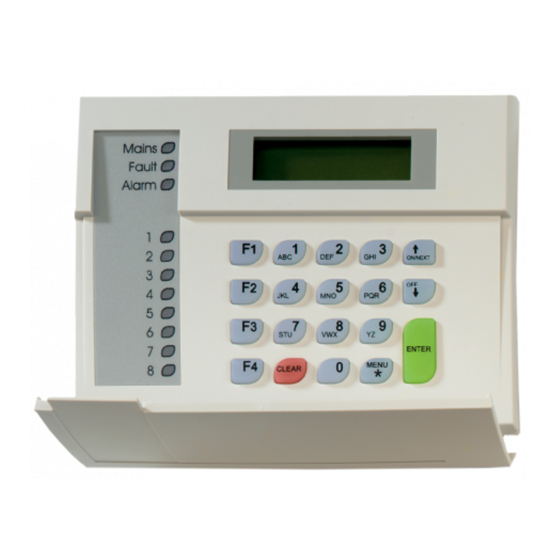
8-Area LCD RAS
M
OUNTING THE UNIT
Please make sure the keypad is mounted on a flat surface, in
order to prevent any incorrect tamper switch actuations.
Attach the mounting box using screws. Secure the PCB with the
screw supplied. Secure the keypad cover with the screw supplied.
When a pry-off tamper is required, use a screw in the back of the
keypad (see figure A,
).
C
ONNECTING THE KEYPAD TO A CONTROL PANEL
Refer to the ATS control panel installation guide for instructions.
LED
(
A)
S
SEE FIGURE
Rx
LED flashes to indicate polling data is being received on
the system databus from the ATS control panel. If the
LED does not flash the control panel is not operational
or the databus is faulty (usually cabling).
Tx
LED flashes to indicate the arming station (RAS) is
replying to polling from the ATS control panel. If the Rx
(Rx0) LED flashes but the Tx (Tx0) LED does not, the
arming station (RAS) is not programmed to be polled in
the control panel or is addressed incorrectly.
LED I
NDICATIONS ON KEYPAD
Area
8 red LED's illuminate when area 1-8 (or 9-16) are
armed. Will blink (armed) or flash (disarmed) on alarm.
Mains
Green LED illuminates if 230 VAC mains power is
available.
Alarm
Red LED illuminates on any alarm in an area assigned to
the keypad.
Fault
Yellow LED illuminates on fault's in the system.
C
(
OMMS CONNECTIONS
FIGURE
Power supply. If the distance between the arming station
+12
and the control panel does not exceed 100m, then the
0V
arming station can be powered using the Comms + and
– from the control panel. Otherwise use AUX PWR from
DGP's or an auxiliary power supply.
D+
Data positive and data negative connection of the
databus.
D -
Remote units can be up to 1.5 km from the
ATS control panel.
IN
A request to exit button (normally open, momentary
push-button switch) can be connected across "IN" and "-
". When pressed, this button controls the request to exit
function.
Rx
Tx
1 2 3 4
1 2 3 4
(
A)
FIGURE
A,
J3)
TERMINAL
© 2003 GE Interlogix B.V.
All rights reserved
SD
ON
1
2 3 4
RAS 1
ON
SD
1
2 3 4
RAS 5
SD
ON
1
2 3 4
RAS 9
ON
SD
1
2 3 4
SW2
RAS 13
OUT
Open collector output, 50 mA maximum. It is the first
output of the output control group that is assigned to this
arming station.
RAS
DIP SWITCH SETTINGS
SW1 DIP switches
These are used to identify the RAS address. See figure B for
settings.
SW2 "A, B, C, Term"
These are used to terminate the databus and enable various other
functions, as described below:
SW2-1, A Area 9-16
OFF
The 8-area LEDs display the status of areas 1 to 8.
ON
The 8-area LEDs display the status of areas 9 to 16.
SW2-2, B Keypad backlight
OFF
The keyboard backlight times out.
ON
The keyboard backlight stays on continuously.
SW2-3, C Magnetic card format (ATS1105 only)
OFF
ATS format
ON
Non-ATS formats.
(e.g., credit cards, any cards with data on track 2).
SW2-4, TERM
OFF
Not the last device on the databus.
ON
Terminates the databus if this RAS is the last device on
the databus. See also the ATS control panel's
installation guide.
R
C
EADERS
ONNECTIONS
+5 V
supply and data connections for ATS magnetic card
readers (ATS1105 only).
1
D1/D Read data pulse / Wiegand D1 line
2
D0/C Read clock pulse / Wiegand D0 line
3
GND (0V)
4
+5 V
5
+12 V
Additional functionality
-
To adjust LCD contrast – Press Menu * and
-
To adjust buzzer volume, press Clear and
and
to decrease the volume
ATS1100/1105
8-Area LCD RAS
SW1 DIP Switch
SD
SD
SD
ON
ON
ON
1
2 3 4
1
2 3 4
1
2 3 4
RAS 2
RAS 3
RAS 4
ON
SD
ON
SD
ON
SD
1
2 3 4
1
2 3 4
1
2 3 4
RAS 6
RAS 7
RAS 8
SD
SD
SD
ON
ON
ON
1
2 3 4
1
2 3 4
1
2 3 4
RAS 10
RAS 11
RAS 12
ON
SD
ON
SD
ON
SD
1
2 3 4
1
2 3 4
1
2 3 4
RAS 14
RAS 15
RAS 16
(
A)
FIGURE
(ATS1105
) (
ONLY
FIGURE
B
A, J2)
or
to increase
1045089
12/2003
Advertisement

Subscribe to Our Youtube Channel
Related Manuals for GE Aritech ATS1100


Summary of Contents for GE Aritech ATS1100
- Page 1 To adjust buzzer volume, press Clear and to increase push-button switch) can be connected across “IN” and “- to decrease the volume “. When pressed, this button controls the request to exit function. © 2003 GE Interlogix B.V. 1045089 All rights reserved 12/2003...
- Page 2 RAS LCD à 8 groupes Clignote pour indiquer que la station d’armement (RAS) ’ ONTAGE DE L UNITE répond à une scrutation provenant de la centrale ATS. Assurez-vous que le clavier soit monté sur une surface plate afin Si le voyant Rx (Rx0) clignote mais pas le voyant Tx d’éviter un mauvais fonctionnement du contact de sabotage.
- Page 3 LED’ De 8-gebieden-LED’s geven de status weer van de ZIE FIGUUR gebieden 1–8. De LED knippert om aan te geven dat er pollgegevens De 8-gebieden-LED’s geven de status weer van de ontvangen worden op de systeemdatabus van het ATS gebieden 9–16. -controlepaneel.
- Page 4 BUS D norme CEI 79-2 2^ ed. questa uscita non può essere ONNESSIONI FIGURA TERMINALE utilizzata per il comando di dispositvi di allarme. Alimentazione. Se la distanza tra la stazione di inserimento e la centrale non supera i 100 m, è possibile ATS1105) ( A, J2) ONNESSIONI LETTORE...
- Page 5 RAS LCD de 8 áreas Output de colector aberto, 50 mA máximo. É a primeira NSTALAÇÃO DA UNIDADE output do grupo de controlo de outputs atribuída a esta Fixe a caixa de instalação utilizando parafusos. Fixe a PCB e a consola de arme.
- Page 6 Bakgrunnsbelysningen på betjeningspanelet slukker OMMUNIKASJONSTILKOBLINGER FIGUR TERMINAL etter en viss tid. Strømforsyning. Hvis avstanden mellom Bakgrunnsbelysningen på betjeningspanelet er alltid på. betjeningspanelet og sentralapparatet ikke overstiger 100 m, kan betjeningspanelet strømforsynes med SW2-3, C Format på magnetkort (kun ATS1105) Comms + og - fra sentralapparatet. I motsatt fall bruker ATS-format du aux-strøm fra US-er eller en ekstern strømforsyning.
- Page 7 Formatos no ATS. D1/D Lectura de pulsos de datos /línea D1 Wiegand. D0/C Lectura de pulsos del reloj / línea D0 Wiegand (por ejemplo, tarjetas de crédito, cualquier tarjeta que GND (0V) contenga datos en la pista 2). +5 V SW2-4, TERM +12 V No es el último dispositivo del bus de datos.
- Page 8 LED blinkar och indikerar att RAS-enheten svarar på SW2 “A, B, C, Term” pollning från ATS-centralapparaten. Om RX (Rx0) Dessa används för att avsluta databussen och möjliggöra andra LED blinkar men TX (Tx0) LED inte blinkar, är RAS- funktioner som framgår nedan. enheten inte programmerad för att pollas i SW2-1, A Område 9–16 centralapparaten.
-
Page 11: Manufacturer's Declaration Of Conformity
GE Interlogix B.V. Kelvinstraat 7 6003 DH Weert, The Netherlands Concerning RTTE Safety Telecom A sample of the product Dare, GE Interlogix, Bicon Dare KTL-Telefication has been tested by: Test report reference QA plan : 00002 Version 2.18h EN50130-4(1995) +A1(1998) EN60950(1992) CTR21(1998) - Page 12 Technical Specifications Technische Specifiche Dane techniczne specifications techniques specificaties tecniche Supply Voltage Tension Voedingsspanning Tensione di Napięcie zasilania 10.5 – 13.8 V nominal d’alimentation alimentazione (12V ) (nominale) Current consumption Consommation Stroomverbruik Assorbimento Pobór prądu max. 185mA. Dimensions (W x H x Dimensions (L x H x Afmetingen (B x H x Dimensioni (l ×...
Need help?
Do you have a question about the Aritech ATS1100 and is the answer not in the manual?
Questions and answers