Table of Contents
Advertisement
Available languages
Available languages
ATTACH YOUR RECEIPT HERE
Serial Number ________________________________ Purchase Date _________________________________
Questions, problems, missing parts? Before returning to your retailer, call our
customer service department at 1-877-447-4768, 8:30 a.m. – 4:30 p.m. CST,
Monday – Friday or e-mail us at customerservice@ghpgroupinc.com.
70-10-560
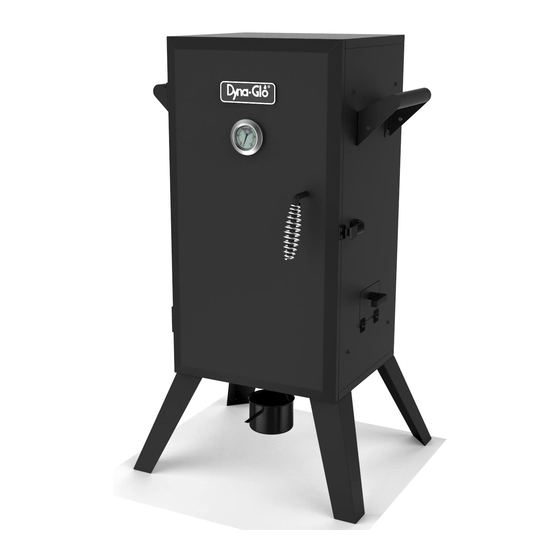
Vertical Electric
Analog Smoker
MODEL #DGU505BAE / DGU505BAE-D
1
Français p. 28
Español p. 55
UL 1026 - sixth edition, 2012
Electric Household
Cooking and Food
Serving Appliances
CSA C22.2 No. 64-10
(reaffirmed 2014)
Household Cooking and
Liquid-Heating Appliances
FOR OUTDOOR
USE ONLY
Use only with Class A GFI
(Ground Fault Interrupter)
Rev. 4/20/16
Advertisement
Chapters
Table of Contents

Subscribe to Our Youtube Channel
Related Manuals for Dyna-Glo DGU505BAE


Summary of Contents for Dyna-Glo DGU505BAE
- Page 1 Vertical Electric Analog Smoker MODEL #DGU505BAE / DGU505BAE-D Français p. 28 Español p. 55 UL 1026 - sixth edition, 2012 Electric Household Cooking and Food Serving Appliances CSA C22.2 No. 64-10 (reaffirmed 2014) Household Cooking and Liquid-Heating Appliances FOR OUTDOOR...
- Page 2 DYNA-GLO VERTICAL GAS SMOKER ® ® DYNA-GLO VERTICAL ELECTRIC ANALOG SMOKER STOP!
-
Page 3: Table Of Contents
TABLE OF CONTENTS Safety Information ...........................3 Package Contents ...........................8 Hardware Contents .........................9 Preparation Before Assembly ......................9 Assembly Instructions ........................10 Operating Instructions ........................17 Tips On Smoking ...........................21 Care and Maintenance ........................23 Troubleshooting ...........................24 Replacement Parts List ........................26 Warranty ............................27 Assembler/Installer: This instruction manual contains important information necessary for the proper assembly and safe use of this appliance. -
Page 4: Safety Information
SAFETY INFORMATION IMPORTANT SAFEGUARDS READ ALL INSTRUCTIONS, PRIOR TO USING THIS SMOKER • DO NOT use this product for anything other than its intended purpose. It is NOT intended for commercial use. It is NOT intended to be installed or used in or on a recreational vehicle and/or boat. •... - Page 5 SAFETY INFORMATION • DO NOT touch hot surfaces. Use handles or knobs. • To protect against electrical shock do not immerse cord, plugs, or thermostat control assembly in water or other liquid. • Close supervision is necessary when any appliance is used by or near children. •...
- Page 6 SAFETY INFORMATION Ground Fault Interrupter • Since 1971 the National Electric Code (NEC) has required Ground Fault Interrupter devices on all outdoor circuits. • If your residence was built before 1971, check with a qualified electrician to determine if a Ground Fault Interrupter protector exists. •...
- Page 7 SAFETY INFORMATION WARNING To Avoid Serious Injury: • While cooking, the smoker must be on a level, stable, noncombustible surface in an area clear of combustible material, including long or dry grass. • The use of alcohol, prescription or nonprescription drugs may impair the user’s ability to properly assemble and safely operate this appliance.
-
Page 8: Package Contents
PACKAGE CONTENTS PART DESCRIPTION QUANTITY Smoker cabinet assembly Side handle Door assembly Door handle assembly Wood chip access door handle Cooking grate Water bowl Wood chip box Wood chip box support Grease cup Heating element assembly Thermostat control assembly Temperature gauge Door latch Door latch bracket Air outlet... -
Page 9: Hardware Contents
HARDWARE CONTENTS #10-24 x 1” #10-24 x ½” ¼”-20 x ½” #10-24 Screw Screw Screw Screw Qty. 2 Qty. 9 Qty. 16 Qty. 4 PREPARATION BEFORE ASSEMBLY Before beginning assembly of product, make sure all parts are present. Compare parts with package contents list and hardware contents above. -
Page 10: Assembly Instructions
ASSEMBLY INSTRUCTIONS CAUTION: This unit is HEAVY! Do not attempt the first 2 steps without assistance! Remove the door assembly (C) by opening and sliding the doors up and off the hinges. With the assistance of a helper, turn the smoker cabinet assembly (A) upside down. - Page 11 ASSEMBLY INSTRUCTIONS Attach each of the side handles (B) to the smoker cabinet assembly (A) using 4 ¼”-20 x ½” screws (AA) per side. Hardware Used ¼”-20 x ½” Screw Attach the door latch (O) to the smoker cabinet assembly (A) using 2 #10-24 x ½” screws (DD). Hardware Used #10-24 x ½”...
- Page 12 ASSEMBLY INSTRUCTIONS Remove the pre-assembled screw from the wood chip access door handle (E) and install the handle (E) on the side access door of the smoker cabinet (A). Attach the heating element assembly (K) to the smoker cabinet assembly (A) using 2 #10-24 x ½”...
- Page 13 ASSEMBLY INSTRUCTIONS Hang the grease cup (J) to the bottom of the smoker cabinet assembly (A). Place water bowl (G) and wood chip box (H) on the wood chip box support (I). Slide the wood chip box support (I) onto the bottom rails of the pre- installed wire supports.
- Page 14 ASSEMBLY INSTRUCTIONS Insert cooking grates (F) on pre-installed wire supports inside the smoker cabinet assembly (A). Firmly insert the thermostat control assembly (L) into the external housing of the heating element assembly (K).
- Page 15 ASSEMBLY INSTRUCTIONS Attach the door handle assembly (D) to the door assembly (C) using 1 #10-24 x ½” screw (DD). Hardware Used #10-24 x ½” Screw Attach the door latch bracket (P) to the door assembly (C) using 2 #10-24 x ½” screws (DD). Hardware Used #10-24 x ½”...
- Page 16 ASSEMBLY INSTRUCTIONS Remove the pre-installed washer and nut from the temperature gauge (M) and insert the probe through the middle hole of the door assembly (C). Secure with pre-assembled washer and nut. Attach the door assembly (C) to the smoker cabinet assembly (A).
-
Page 17: Replacement Parts List
REPLACEMENT PARTS LIST For replacement parts, call our customer service department at 1-877-447-4768, 8:30 a.m. - 4:30 p.m. CST, Monday - Friday or e-mail us at customerservice@ghpgroupinc.com. PART DESCRIPTION PART # PART DESCRIPTION PART # Air Outlet Tube Smoker Cabinet Assembly 70 - 01 - 375 Assembly... - Page 18 Fumoir Numérique Électrique Vertical MODÈLE #DGU505BAE / DGU505BAE-D UL 1026 - sixième édition, 2012 Appareils ménagers pour cuisson et appareils de service alimentaire CSA C22.2 No. 64-10 (Réaffirmé 2014) Appareils ménagers pour cuisson et appareils à cuisson liquide POUR USAGE EXTÉRIEUR SEULEMENT...
- Page 19 ® DYNA-GLO FUMOIR NUMÉRIQUE ÉLECTRIQUE VERTICAL ARRÊT! NUL BESOIN DE REVENIR AU MAGASIN Questions sur l’assemblage? Besoin d’information sur des pièces? Le produit est couvert par la garantie des fabricants? Composez le numéro sans frais : 1 877 447-4768 du lundi au vendredi de 8 h 30 h à 16 h 30, HNC Conservez ce Manuel du propriétaire et votre preuve d’achat en cas de besoin...
- Page 20 TABLE DES MATIÈRES Consignes de sécurité ........................30 Contenu de l’emballage .........................35 Quincaillerie incluse ........................36 Préparation avant l’assemblage.....................36 Instructions pour l’assemblage ....................37 Mode d’emploi ..........................44 Conseils sur le tabagisme ......................48 Entretien ............................50 Dépannage ..........................51 Liste des pièces de rechange .......................53 Garantie ............................55 Assembleur / installateur: Ce manuel d'instructions contient des informations importantes nécessaires à...
-
Page 21: Consignes De Sécurité
CONSIGNES DE SÉCURITÉ PRÉCAUTIONS IMPORTANTES LIRE TOUTES LES INSTRUCTIONS AVANT D’UTILISER CE FUMOIR • NE PAS utiliser ce produit pour autre chose que sa raison principale. Il n’est PAS destiné à l’usage commercial. Il n’est PAS destiné à être installé ou utiliser sur ou dans un véhicule récréatif ou/et bateau. - Page 22 CONSIGNES DE SÉCURITÉ • Une supervision assidue est requise lorsque l’appareil est utilisé près ou par des enfants. • Débrancher de la prise lorsque l’appareil n’est pas utilisé ou avant de nettoyer. Attendre que l’appareil soit complétement refroidi avant de remettre ou détacher des pièces. •...
- Page 23 CONSIGNES DE SÉCURITÉ Circuit Interrupteur de terre • Depuis 1971, le code èlectrique national (CÈN) requiert des circuits interrupteurs de terre sur tout circuit extèrieur. • Si votre rèsidence a ètè batie avant 1971, vèrifiè avec un èlectricien qualifiè afin de dèterminer si un circuit interrupteur de terre existe.
- Page 24 CONSIGNES DE SÉCURITÉ AVERTISSEMENT Afin d’éviter des blessures graves: • Lors de la cuisson, le fumoir doit être sur une surface égale et stable, ininflammable dans un endroit loin de matériaux combustibles, incluant de l’herbe sèche ou longue. • L’usage d’alcool, médicaments prescrits ou sans ordonnance peuvent altérer les décisions de l’utilisateur lors de l’assemblage et lors de l’opération de cet appareil.
-
Page 25: Contenu De L'emballage
CONTENU DE L’EMBALLAGE PIECE DESCRIPTION PIECE DESCRIPTION Assemblage du cabinet Plateau à graisse du fumoir Assemblage de l’élément Poignée de derrière de chaleur Assemblage de la porte Assemblage du contrôle Poignée de porte du thermostat Poignée de porte d’accès Indicateur de température Pied aux éclisses de bois Grilles de cuisson... -
Page 26: Quincaillerie Incluse
QUINCAILLERIE INCLUSE #10-24 x 1” #10-24 x ½” ¼”-20 x ½” #10-24 Écrou Qte. 2 Qte. 9 Qte. 16 Qte. 4 PRÉPARATION AVANT L’ASSEMBLAGE Avant de commencer l’assemblage du produit, assurez-vous d’avoir toutes les pièces. Comparez les pièces dans l’emballage avec la liste des pièces de la page précédente et la quincaillerie indiquée ci-dessus. -
Page 27: Instructions Pour L'assemblage
INSTRUCTIONS POUR L’ASSEMBLAGE ATTENTION: Cette pièce est LOURDE! Ne pas compléter les 2 premières étapes sans aide! Enlever l’assemblage de la porte (C) en ouvrant et glissant les portes par en haut et hors des pentures. Avec l’aide d’une autre personne, tourner le cabinet du fumoir (A) à... - Page 28 INSTRUCTIONS POUR L’ASSEMBLAGE Attacher chacune des poignées de côté (B) à l’assemblage du cabinet du fumoir (A) en utilisant 4 visses ¼”-20 x ½” (AA) par côté. Quincaillerie utilisée ¼”-20 x ½” Attacher le loquat de la porte (O) à l’assemblage du cabinet du fumoir (A) en utilisant 2 visses #10- 24 x ½”...
- Page 29 INSTRUCTIONS POUR L’ASSEMBLAGE Dévisser les vises préassemblées de la poignée de porte pour les éclisses de bois (E) et installer la poignée (E) sur la porte pour éclisses de bois sur le côté de la porte d'accès du cabinet du fumoir (A). Attacher les pièces de chauffage (K) à...
- Page 30 INSTRUCTIONS POUR L’ASSEMBLAGE Affixer la tasse à graisse (J) au bas de l’assemblage du cabinet du fumoir (A). Placer le bol d’eau (G) et le boîtier aux éclisses de bois (H) sur le support des boîtiers (I). Glisser le support (I) sur le bas des rails des fils électriques préinstallés sur leur supports.
- Page 31 INSTRUCTIONS POUR L’ASSEMBLAGE Insérer les grilles de cuisson (F) sur les supports de fils préinstallés à l’intérieur du cabinet du fumoir (A). Insérer fermement l’assemblage du contrôle du thermostat (L) dans le boîtier de l’assemblage de l’élément de chaleur extérieur (K).
- Page 32 INSTRUCTIONS POUR L’ASSEMBLAGE Fixer l’assemblage de la poignée de la porte (D) à l’assemblage de la porte (C) en utilisant 1 visse #10-24 x ½” (DD). Quincaillerie utilisée #10-24 x ½” Fixer le crochet du loquet (P) à l’assemblage de la porte (C) avec 2 visses #10-24 x ½”...
- Page 33 INSTRUCTIONS POUR L’ASSEMBLAGE Enlever la rondelle et l’écrou préinstallés de la gauge à température (M) et insérer la sonde dans le trou du centre de l’assemblage de la porte (C). Sécuriser avec la rondelle et l’écrou préassemblés. Fixer l’assemblage de la porte (C) à l’assemblage du cabinet du fumoir (A).
-
Page 34: Liste Des Pièces De Rechange
LISTE DES PIÈCES DE RECHANGE Pour les pièces détachées, appelez notre service à la clientèle au 1-877-447-4768, 8 heures 30-16h30, HNC, du lundi - vendredi. RÉF DESCRIPTION NO DE PIÈCE RÉF DESCRIPTION NO DE PIÈCE Poignée pour l’accès au Assemblage du cabinet du fumoir 70 - 01 - 375 boîtier d’éclisses de bois... - Page 35 LISTE DES PIÈCES DE RECHANGE 70-10-560 Impreso en China...
- Page 36 Ahumador Analógico Eléctrico Vertical MODELO #DGU505BAE / DGU505BAE-D UL 1026 - sexta edicion, 2012 Electrodomésticos de Unidad Familiar y Aparatos de Servir Comida CSA C22.2 No. 64-10 (reafirmado 2014) Cocina de Unidad familiar y Aparatos de Calentador Líquidos PARA USO EXTERNO...
- Page 37 ® DYNA-GLO AHUMADOR ANALÓGICO ELÉCTRICO VERTICAL ¡PARE! NO TIENE QUE REGRESAR A LA TIENDA ¿Tiene preguntas respecto al ensamblaje? ¿Necesita información sobre las piezas? ¿Se encuentra el producto bajo garantía del fabricante? Llame gratis al: 1-877-447-4768 8:30 a.m. – 4:30 pm Hora del Centro, de lunes a viernes...
- Page 38 INDICE Informacion de seguridad ......................58 Contenido del paquete ........................63 Aditamentos .............................64 Preparación Antes del Ensamblado ....................64 Instrucciones de ensamblaje .......................65 Instrucciones de funcionamiento ....................72 Consejos para fumar ........................76 Cuidado y mantenimiento ......................78 Solución de problemas .........................79 Lista de piezas de repuesto ......................81 Garantla ............................83 Ensamblador / instalador: Este manual de instrucciones contiene información importante necesaria para el correcto montaje y el uso seguro de este aparato.
-
Page 39: Informacion De Seguridad
INFORMACION DE SEGURIDAD PRECAUCIONES IMPORTANTES LEA TODAS LAS INSTRUCCIONES, ANTES DE UTILIZAR ESTE AHUMADOR • NO utilice este producto para algo que no sea su proposito. NO es para uso comercial. NO está destinado a ser instalado o utilizado en o sobre un vehículo y / o barco recreativo. •... - Page 40 INFORMACION DE SEGURIDAD • Para protegerse contra descargas eléctricas, no sumerja el cable, los enchufes, o conjunto de control del termostato en agua u otro líquido. • Se requiere supervisión cuando cualquier aparato es utilizado por o cerca de niños. •...
- Page 41 INFORMACION DE SEGURIDAD Interruptor de falla a tierra • Desde 1971 el codigo electrico nacional (NEC) exige dispositivos de GFCI entodos los circuitos al aire libre. • Si su vivienda fue construida antes de 1971, consulte con un electricist acalificado det determinar si existe.
- Page 42 INFORMACION DE SEGURIDAD ADVERTENCIA Para evitar lesiones graves: • Durante la coccion, el ahumador debe estar sobre una superficie nivelada, estable y incombustible en un area libre de material combustible, incluyendo hierba larga o seco. • El uso de alcohol, prescripción o medicamentos de venta libre pueden afectar la capaci dad del usuario para armar correctamente y operar con seguridad este aparato.
-
Page 43: Contenido Del Paquete
CONTENIDO DEL PAQUETE PIECE DESCRIPTION PIECE DESCRIPTION Conjunto del Gabinete Recipiente de Grasa del Ahumador Conjunto de elementos Manilla Trasera de calentamiento Conjunto de Puerta Conjunto de control Manilla de la Puerta del termostato Manilla de puerta de astilla Indicador de temperatura Pata de madera de acceso Parillas de coccion... -
Page 44: Aditamentos
ADITAMENTOS (PRE-ENSAMBLADOS) ¼”-20 x ½” #10-24 x 1” #10-24 #10-24 x ½” Tornillo Tornillo Tuerca Tornillo Cant. 2 Cant. 9 Cant. 16 Cant. 4 PREPARACIÓN ANTES DEL ENSAMBLADO Antes de comenzar a ensamblar el praducto, asegurese de tener todas las piezas. Compare las piezas con la lista del contenido del paquete de la pagina anterior y los aditamentos que aparecen arriba. -
Page 45: Instrucciones De Ensamblaje
INSTRUCCIONES DE ENSAMBLAJE PRECAUCIÓN: Esta unidad es PESADA! No intente los 2 primeros pasos sin assistencia! Retire el conjunto de la puerta (C) abriendo y deslizando las puertas hacia arriba y hacia afuera de las bisagras. Con la asistencia de un ayudante, gire el conjunto del gabinete del ahumador (A) boca abajo. - Page 46 ASSEMBLY INSTRUCCIONES DE ENSAMBLAJE Coloque cada una de las asas laterales (B) al conjunto del gabinete del ahumador (A) con 4 ¼ "-20 x ½" tornillos (AA) por lado. Aditamentos utilizados ¼”-20 x ½” Tornillo Fije el cierre de la puerta (O) para el conjunto del gabinete del ahumador (A) utilizando 2 # 10- 24 x ½"...
- Page 47 INSTRUCCIONES DE ENSAMBLAJE Retire el tornillo de pre-ensamblado de la manilla de puerta de astilla de madera de acceso (E) y instale la manilla (E) en la puerta de acceso lateral del gabinete del ahumador (A). Conecte el conjunto del elemento de calentamiento (K) para el conjunto del gabinete del ahumador (A) utilizando 2 # 10-24 x ½...
- Page 48 INSTRUCCIONES DE ENSAMBLAJE Cuelgue el recipiente para la grasa (J) a la parte inferior del conjunto del gabinete del ahumador (A). Coloque un tazón de agua (G) y depósito de astillas de madera (H ) en el soporte de depósito de las astillas de madera (I).
- Page 49 INSTRUCCIONES DE ENSAMBLAJE Inserte las parrillas de cocción (F) en el soporte del alambre pre-instalado dentro del conjunto del gabinete del ahumador (A). Inserte firmemente el conjunto de control del termostato (L) en la carcasa externa delconjunto del elemento de calentamiento (K).
- Page 50 INSTRUCCIONES DE ENSAMBLAJE Fije el conjunto de la manilla de la puerta (D) para el conjunto de la puerta (C) utilizando 1 # 10-24 x ½ " tornillo (DD). Aditamentos utilizados #10-24 x ½” Tornillo Fije el soporte de cierre de la puerta (P) al conjunto de la puerta (C) utilizando 2 # 10-24 x ½...
- Page 51 INSTRUCCIONES DE ENSAMBLAJE Retire la arandela pre-instalada y la tuerca del indicador de temperatura (M) e insertar la sonda a través del agujero central del conjunto de la puerta (C). Asegure con la arandela pre-ensamblada y la tuerca. Adjunte el conjunto de la puerta (C) al conjunto del gabinete del ahumador (A).
-
Page 52: Lista De Piezas De Repuesto
LISTA DE PIEZAS DE REPUESTO Para obtener piezas de repuesto, llame a nuestro Departamento de Servicio al Cliente al 1-877-447-4768, de 8:30 am - 4:30 pm, hora central, de lunes - viernes. REF. DESCRIPCIÓN PIEZA # REF. DESCRIPCIÓN PIEZA # Manilla de puerta de Conjunto del gabinete del Ahumador... - Page 53 LISTA DE PIEZAS DE REPUESTO 70-01-560 Imprime in China...
Need help?
Do you have a question about the DGU505BAE and is the answer not in the manual?
Questions and answers