Table of Contents
Advertisement
Available languages
Available languages
Quick Links
Operator's Manual
Electric Start
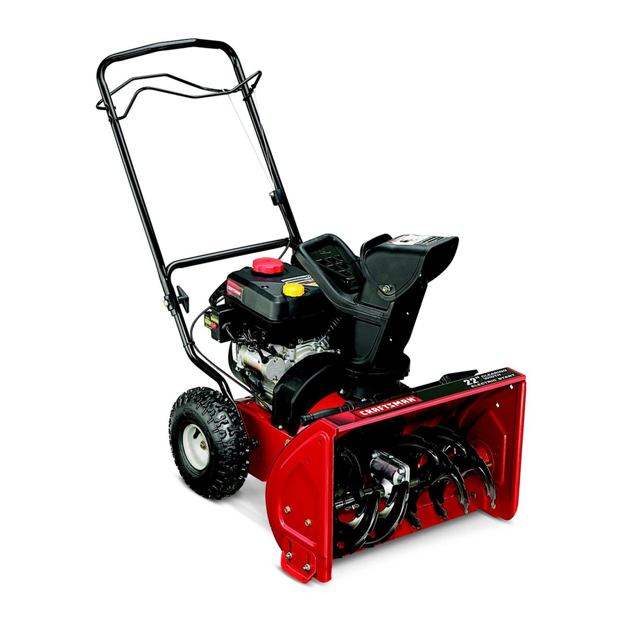
22-INCH SNOW THROWER
Model No. 247.88779
CAUTION: Before using
this product, read this
manual and follow all
safety rules and operating
instructions.
Sears, Roebuck and Co., Hoffman Estates, IL 60179, U.S.A.
Visit our website: www.sears.com/craftsman
®
• SAFETY
• ASSEMBLY
• OPERATION
• MAINTENANCE
• PARTS LIST
• ESPANOL
FORM NO. 769-05101
6/17/2009
Advertisement
Chapters
Table of Contents

Related Manuals for Craftsman 247.88779


Summary of Contents for Craftsman 247.88779
- Page 1 Operator’s Manual ® Electric Start 22-INCH SNOW THROWER Model No. 247.88779 • SAFETY • ASSEMBLY • OPERATION CAUTION: Before using • MAINTENANCE this product, read this • PARTS LIST manual and follow all • ESPANOL safety rules and operating instructions.
-
Page 2: Table Of Contents
When operated and maintained according to all supplied instructions, if this Craftsman snow thrower fails due to a defect in material or workmanship within two years from the date of purchase, return it to any Sears store, Sears Parts & Repair Service Center, or other Craftsman outlet in the United States for free repair (or replacement if repair proves impossible). -
Page 3: Safe Operation Practices
SAFETY INSTRUCTIONS WARNINg DANgER This machine was built to be operated according to the safe opera- This symbol points out important safety instructions which, if not tion practices in this manual. As with any type of power equipment, followed, could endanger the personal safety and/or property of carelessness or error on the part of the operator can result in serious yourself and others. - Page 4 SAFETY INSTRUCTIONS Safe Handling of Gasoline • Exercise extreme caution when operating on or crossing gravel surfaces. Stay alert for hidden hazards or traffic. To avoid personal injury or property damage use extreme care in handling gasoline. Gasoline is extremely flammable and the vapors are •...
- Page 5 SAFETY INSTRUCTIONS MAINTENANCE & SToRAgE Do NoT MoDIFY ENgINE • Never tamper with safety devices. Check their proper operation To avoid serious injury or death, do not modify engine in any way. regularly. Refer to the maintenance and adjustment sections of Tampering with the governor setting can lead to a runaway engine and this manual.
- Page 6 SAFETY INSTRUCTIONS SAFETY SYMboLS This page depicts and describes safety symbols that may appear on this product. Read, understand, and follow all instructions on the machine before attempting to assemble and operate. Symbol Description READ THE OPERATOR’S MANUAL(S) Read, understand, and follow all instructions in the manual(s) before attempting to assemble and operate WARNING—...
-
Page 7: Safety Labels
SAFETY LABELS... -
Page 8: Assembly
ASSEMBLY IMPORTANT: This unit is shipped with the engine full of oil. After assembly, see page 10 for fuel and oil details. Removing From Carton 1. Cut the corners of the carton and lay the sides flat on the ground. Remove all packing inserts. - Page 9 ASSEMBLY Skid Shoe Clean-out Tool The snow thrower skid shoes are adjusted upward at the factory for shipping The chute clean-out tool is fastened to the top of the auger housing with a purposes. Adjust them downward, if desired, prior to operating the snow mounting clip and a cable tie at the factory.
- Page 10 ASSEMBLY Fuel Recommedations Checking oil Level Use automotive gasoline (unleaded or low leaded to minimize combus- CAUTIoN tion chamber deposits) with a minimum of 87 octane. Gasoline with The engine is shipped with oil in the engine. You must, however, up to 10% ethanol or 15% MTBE (Methyl Tertiary Butyl Ether) can be check the oil level prior to operating the snow thrower.
- Page 11 ASSEMBLY Discharge Chute Auger Control Test IMPORTANT: Perform the following test before operating the snow Loosen the wing knob on the upper chute, adjust chute and chute control to desired operating position. thrower for the first time and at the start of each winter season. Tighten the wing knob on the upper chute making sure the carriage bolt Check the adjustment of the auger control as follows: is correctly positioned.
-
Page 12: Operation
Operation Upper Handle Drive Auger Control Control Upper Chute Chute Handle Fuel Cap Muffler Chute Assembly Recoil Starter Handle Clean-out Tool Oil Cap Primer Throttle Control Electric Starter Choke Button Chute Knob Control Auger Shave Plate Electric Starter Outlet Oil Drain Skid Shoe WARNINg Be familiar with all the controls on the snow thrower and their proper operation. - Page 13 Operation Auger Clean-out Tool When engaged, the auger rotates and draws snow into the auger WARNINg housing. Never use your hands to clear a clogged chute assembly. Shut off Chute Assembly engine and remain behind handles until all moving parts have stopped Snow drawn into the auger housing is discharged out the chute before using the clean-out tool to clear the chute assembly.
- Page 14 Operation gasoline Determine that your home’s wiring is a three-wire grounded system. Ask a licensed electrician if you are not certain. Use automotive gasoline (unleaded or low leaded to minimize combus- If you have a grounded three-prong receptacle, proceed as follows. tion chamber deposits) with a minimum of 87 octane.
- Page 15 Operation Positioning Discharge Chute Stopping The Engine Run engine for a few minutes before stopping to help dry off any Loosen the chute knob and pivot upper chute to desired position. Tighten moisture on the engine. the chute knob making sure the carriage bolt is correctly positioned. Move throttle control to STOP position.
-
Page 16: Maintenance & Service
Maintenance & Service WARNINg Follow the maintenance schedule given below. This chart describes service guidelines only. Use the Service Log column to keep track Before servicing, repairing, lubricating or inspecting, disengage all of completed maintenance tasks. To locate the nearest Sears controls and stop engine. - Page 17 Maintenance & Service Reinstall the drain plug and tighten it securely. Refill with the recommended oil and check the oil level. Recommended Oil Usage chart. The engine’s oil capacity is 20 ounces. Synthetic 0W-30 5W-30 -40º -20º 0º 20º 40º Oil Drain -30º...
- Page 18 Maintenance & Service general Recommendations Servicing Auger 1. Always observe safety rules when performing any maintenance. The auger is secured to the spiral shaft with four shear pins and cotter 2. The warranty on this snow thrower does not cover items that have pins.
- Page 19 Maintenance & Service Replacing belts NOTE: There are two belts on this snow thrower: an auger belt and drive belt. It is recommended that both belts be replaced at the same time. 1. Remove the spark plug wire from spark plug and ground it against the engine to prevent accidental starting.
- Page 20 Maintenance & Service 6. Tilt the transmission forward and position the drive belt onto the transmission pulley. 7. Reconnect the spring to the bolt on the engine frame and secure the transmission. Reinstall the flange lock nut. 8. Install new auger belt. 9.
-
Page 21: Off-Season Storage
OFF-SEASON STORAGE If the snow thrower will not be used for 30 days or longer, or if it is the end of the snow season when the last possibility of snow is gone, the equipment needs to be stored properly. Follow storage instructions below to ensure top performance from the snow thrower for many more years. PREPARINg SNoW THRoWER PREPARINg ENgINE •... -
Page 22: Troubleshooting
TROUBLESHOOTING This section addresses minor service issues. To locate the near- WARNINg est Sears Service Center or to schedule service, simply contact Before performing any type of maintenance/service, disengage all Sears at 1-800-4-MY-HOME®. controls and stop the engine. Wait until all moving parts have come to a complete stop. -
Page 23: Parts List
Parts List Craftsman Snow Thrower Model 247.88779 777S32636 777X43688 777I22164 777S32236 777I23249 777I22138 777D12682 777D12657 777D11429... - Page 24 Parts List Craftsman Snow Thrower Model 247.88779...
- Page 25 Parts List Craftsman Snow Thrower Model 247.88779 PART NUMBER DESCRIPTION PART NUMBER DESCRIPTION 984-04037 Chute Assembly 731-04218B Impeller 710-04071 Carriage Bolt 5/16-18 x 1.0” 932-0611 Extension Spring 710-0451 Carriage Bolt 5/16-18 736-0174 Wave Washer 710-0260A Carriage Bolt 5/16-18 x .62...
- Page 26 Parts List Craftsman Snow Thrower Model 247.88779...
- Page 27 Parts List Craftsman Snow Thrower Model 247.88779 Ref. No. Part No. Description Ref. No. Part No. Description 710-0572 Carriage Screw 5/16-18 x 2.25 756-0625 Cable Roller 710-0605 Mach. Screw 1/4-20 x 1.825 784-0419C-0721 Drive Housing Frame 710-04484 Screw 5/16-18 x .75...
- Page 28 PARTS LIST Craftsman Engine Model ZS365-SUB For Snow Thrower Model 247.88779 109 117 69 64 13 14 37 37...
- Page 29 PARTS LIST Craftsman Engine Model ZS365-SUB For Snow Thrower Model 247.88779 Ref. Part No. Description Ref. Part No. Description 951-11012 Bolt 951-11371 Crankcase Cover Gasket 951-11054 Valve Cover 710-04932 Cover Bolt 731-07059 Breather Hose 951-11368 Oil Seal 726-04101 Hose Clamp...
- Page 30 PARTS LIST Craftsman Engine Model ZS365-SUB For Snow Thrower Model 247.88779 Ref. Part No. Description Qty. Ref. Part No. Description Qty. 715-04088 Dowel Pin — 951-11061A Gasket Kit, Complete (Not Shown) — 951-10645A Electric Starter — Head Cover Gasket 710-05003...
- Page 31 PARTS LIST Craftsman Engine Model ZS365-SUB For Snow Thrower Model 247.88779 Ref. Part No. Description Qty. Ref. Part No. Description Qty. — 951-11020 Carburetor Kit, Major (Not Shown) — — 951-11062A Short Block Assembly (Not Shown) — — Gasket, Throttle Plate —...
- Page 32 MTD CoNSUMER gRoUP INC (MTD), the California Air Resources board (CARb) and the United States Environment Protection Agency (U. S. EPA) Emission Control System Warranty Statement (owner’s Defect Warranty Rights and obligations) EMISSION CONTROL SYSTEM COVERAGE IS APPLICABLE TO CERTIFIED ENGINES PURCHASED IN CALIFORNIA IN 2005 AND THERE- AFTER, WHICH ARE USED IN CALIFORNIA, AND TO CERTIFIED MODEL YEAR 2005 AND LATER ENGINES WHICH ARE PURCHASED AND USED ELSEWHERE IN THE UNITED STATES.
- Page 33 (4) Repair or replacement of any warranted part under the warranty provisions of this article must be performed at no charge to the owner at a warranty station. (5) Notwithstanding the provisions of Subsection (4) above, warranty services or repairs must be provided at all MTD distribution centers that are franchised to service the subject engines.
- Page 34 Look For Relevant Emissions Durability Period and Air Index Information on Your Engine Emissions Label Engines that are certified to meet the California Air Resources Board (CARB) Tier 2 Emission Standards must display information regarding the Emissions Durability Period and the Air Index. Sears, Roebuck and Co., U.S.A. makes this information available to the consumer on our emission labels.
-
Page 35: Repair Protection Agreement
REPAIR PROTECTION AGREEMENT Congratulations on making a smart purchase. Your new Craftsman® Once you purchase the Agreement, a simple phone call is all that it product is designed and manufactured for years of dependable opera- takes for you to schedule service. You can call anytime day or night, or tion. -
Page 36: Español
ÍNDICE Declaración de garantía ......Página 35 Solución de problemas ......Página 55 Prácticas operación seguras .....Página 36 Etiquetas de seguridad ......Página 56 Montaje ............Página 40 Lista de piezas ...........Página 58 Operación ..........Página 44 Acuerdo de protección para reparaciones ..Página 59 Servicio y Mantenimiento ......Página 48 Número de servicio ........Cubierta posterior Almacenamiento fuera de temporada ..Página 53... - Page 37 INSTRUCCIONES DE SEGURIDAD ADVERTENCIA PELIgRo Esta máquina fue construida para ser operada de acuerdo con La presencia de este símbolo indica que se trata de instrucciones las reglas de seguridad contenidas en este manual. Al igual que importantes de seguridad que se deben respetar para evitar con cualquier tipo de equipo motorizado, un descuido o error por poner en peligro su seguridad personal y/o material y la de otras parte del operador puede producir lesiones graves.
- Page 38 INSTRUCCIONES DE SEGURIDAD Manejo seguro de la gasolina • Nunca opere la máquina si falta un montaje del canal o si el mismo está dañado. Mantenga todos los dispositivos de seguri- Para evitar lesiones personales o daños materiales tenga mucho dad en su lugar y en funcionamiento.
- Page 39 INSTRUCCIONES DE SEGURIDAD • Para encender el motor, jale de la cuerda lentamente hasta que • Según la Comisión de Seguridad de Productos para el Consu- sienta resistencia, luego jale rápidamente. El repliegue rápido de midor de los Estados Unidos (CPSC) y la Agencia de Protección la cuerda de arranque (tensión de retroceso) le jalará...
- Page 40 INSTRUCCIONES DE SEGURIDAD SíMboLoS DE SEgURIDAD Esta página describe los símbolos y figuras de seguridad internacionales que pueden aparecer en este producto. Lea el manual del operador para obtener la información terminada sobre seguridad, reunirse, operación y mantenimiento y reparación. Símbolo Descripción LEA EL MANUAL DEL OPERADOR (S)
-
Page 41: Montaje
MONTAJE IMPORTANTE: Esta unidad se envía con el motor lleno de aceite. Después del montaje, consulte la página 10 para los detalles del combustible y el aceite. Extracción de la unidad de la caja 1. Corte las esquinas de la caja de cartón y extienda los lados de manera que queden planos sobre el piso Quite todos los separadores de empaque. - Page 42 MONTAJE Zapata antideslizante Pasadores de cuchilla Las zapatas antideslizantes de la máquina quitanieve se ajustan hacia arriba Su máquina quitanieve trae un par de pasadores en fábrica, para el envío. Si lo desea, puede ajustarlas hacia abajo antes de de cuchilla de la barrena y pasadores de chaveta hacer funcionar la máquina quitanieve.
- Page 43 MONTAJE Recomendaciones sobre el combustible Verificación del nivel de aceite Utilice gasolina para automóviles (sin plomo o bajo contenido de plomo PRECAUCIóN para minimizar los depósitos en la cámara de combustión) con un mínimo El motor se envía con aceite en el motor. Sin embargo, debe de 87 octanos.
- Page 44 MONTAJE Canal de descarga Si la barrena muestra ALGÚN signo de rotación, vuelva inmediatamente a la posición del operador y apague el motor. Afloje la perilla de aletas del canal superior, ajuste el canal y el control Espere a que todas las partes móviles se detengan antes de del canal a la posición de funcionamiento deseada.
-
Page 45: Operación
Funcionamiento Upper Handle Barra de control superior Auger Control Control de la barrena Control de la Drive transmisión Control Cuerda de Tapa de la Starter Rope Gasoline Cap arranque gasolina Chute Handle Manija del canal Upper Chute Canal superior Tapón de Fuel Cap Manija del combustible... - Page 46 Funcionamiento barrenas El control del regulador está ubicado en el motor. Regula la velocidad del motor, y lo apaga cuando se presiona hacia abajo completamente. Cuando están engranadas, las barrenas giran y mandan la nieve hacia La imagen de la derecha representa las velocidades del control el interior de la caja de la barrena.
- Page 47 Funcionamiento gasolina NO use el arrancador eléctrico en ninguna circunstancia. Conecte el prolongador a la salida situada en la superficie del motor. Utilice gasolina para automóviles (sin plomo o bajo contenido de plomo Conecte el otro extremo del prolongador a un tomacorriente de CA, para minimizar los depósitos en la cámara de combustión) con un mínimo 120 voltios con conexión a tierra, para tres patas, en un área bien de 87 octanos.
- Page 48 Funcionamiento Ubicación del canal de descarga Detención del motor Deje encendido el motor durante algunos minutos antes de detenerlo para Afloje la perilla del canal y gire el canal superior hasta la posición deseada. permitir que se seque la humedad en el mismo. Ajuste la perilla del canal comprobando que el perno de carro esté...
- Page 49 Mantenimiento y servicio MANTENIMIENTo DEL MoToR ADVERTENCIA Antes de realizar tareas de lubricación, reparación o inspección, desengrane todos los controles y detenga el motor. Espere a que se detengan completamente todas las piezas móviles. Control del aceite del motor NOTA: Verifique el nivel de aceite antes de cada uso y después de cada cinco horas de funcionamiento para cerciorarse que se mantiene el nivel de aceite indicado.
- Page 50 Mantenimiento y servicio Control de la bujía ADVERTENCIA Bujía de encendido NO pruebe la chispa si no está la bujía de encendido. NO dé arranque al motor si no está la bujía de encendido. ADVERTENCIA Si el motor ha estado funcionando, el silenciador estará muy caliente. Tenga cuidado de no tocar el silenciador.
- Page 51 Mantenimiento y servicio Recomendaciones generales Pasador de Pasador de cuchilla 1. Respete siempre las reglas de seguridad cuando realice tareas de chaveta Zapata mantenimiento. antideslizante 2. La garantía de esta máquina quitanieve no cubre elementos que han estado sujetos al mal uso o negligencia del operador. Para recibir el reembolso total de la garantía, el operador deberá...
- Page 52 Mantenimiento y servicio ADVERTENCIA Antes de realizar tareas de servicio, reparación, lubricación o inspección, desengrane todos los controles y detenga el motor. Espere a que se detengan completamente todas las piezas móviles. Desconecte el cable de la bujía y póngalo haciendo masa contra el motor para evitar que se encienda accidentalmente.
- Page 53 Mantenimiento y servicio Ajuste del cable de la barrena Es posible que se requieran ajustes periódicos del cable de control de la barrena debido al estiramiento y al desgaste normal de la correa. Se necesitarán ajustes si las barrenas parecen temblar mientras giran pero el motor mantiene su velocidad, o si sigue girando con el control de la barrena desengranado.
-
Page 54: Almacenamiento Fuera De Temporada
ALMACENAMIENTO FUERA DE TEMPORADA Si no se va a utilizar el equipo durante 30 días o más, o si es el final de la temporada de nieve y ya no existe posibilidad de que nieve, es necesario almacenar el equipo de manera adecuada. Siga las instrucciones de almacenamiento que se indican a continuación para garantizar el rendimiento máximo de la máquina quitanieve durante muchos años más. -
Page 55: Solución De Problemas
SOLUCIÓN DE PROBLEMAS ADVERTENCIA Antes de realizar cualquier tipo de mantenimiento o servicio, desenganche todos los controles y detenga el motor. Espere a que se detengan comple- tamente todas las piezas móviles. Desconecte el cable de la bujía y póngalo haciendo masa contra el motor para evitar que se encienda accidentalmente. - Page 56 MTD CoNSUMER gRoUP, INC. (MTD), el bordo de Recursos de Aire de California (CARb) y la Agencia de Protección Medioambiental de Estados Unidos (U. S. EPA) Declaración de garantía del Sistema de Control de Emisiones (Derechos y obligaciones del propietario según la garantía contra defectos) LA COBERTURA DE SISTEMA DE CONTROL DE EMISIÓN ES APLICABLE A MOTORES CERTIFICADOS COMPRADOS EN CALIFORNIA EN 2005 Y A PARTIR DE ENTONCES, QUE SON USADOS EN CALIFORNIA, Y HASTA AÑO 2005 DE MODELO CERTIFICADO Y MOTORES POSTERIORES QUE SON COMPRADOS Y USADOS EN OTRA PARTE EN LOS ESTADOS UNIDOS.
- Page 57 reemplazada según la garantía se garantizará por el resto del período de garantía. Cualquier pieza garantizada que esté programada para reemplazo según el mantenimiento requerido de conformidad con las instruc- ciones escritas de la Subsección (c) se garantiza por el período de tiempo anterior a la primera fecha de reemplazo programada para esa pieza.
- Page 58 busque el período de duración de emisiones importantes yla información de clasificación de aire en la etiqueta de emisiones de su motor Los motores cuyo cumplimiento con los estándares de emisión Tier 2 de la Comisión de Recursos Ambientales de California (CARB) esté...
-
Page 59: Acuerdo De Protección Para Reparaciones
Felicitaciones por haber realizado una adquisición inteligente. El Una vez adquirido el Acuerdo, puede programar el servicio con producto Craftsman® que ha adquirido está diseñado y fabricado tan sólo realizar una llamada telefónica. Puede llamar en cualquier para brindar muchos años de funcionamiento confiable. Pero como momento del día o de la noche o programar un servicio en línea. - Page 60 Your Home For expert troubleshooting and home solutions advice: www.managemyhome.com For repair – in your home – of all major brand appliances, lawn and garden equipment, or heating and cooling systems, no matter who made it, no matter who sold it! For the replacement parts, accessories and owner’s manuals that you need to do-it-yourself.
Need help?
Do you have a question about the 247.88779 and is the answer not in the manual?
Questions and answers