Table of Contents
Advertisement
IMPORTANT - READ BEFORE INSTALLING
1. Read and become familiar with these installation in-
structions before installing this unit.
2. Be sure the installation conforms to all applicable local
and national codes.
3. These instructions contain important information for the
proper maintenance and repair of this equipment. Re-
tain these instructions for future use.
CONTENTS
SAFETY CONSIDERATIONS . . . . . . . . . . . . . . . . . . . . . . . 1
INSTALLATION . . . . . . . . . . . . . . . . . . . . . . . . . . . . . . . . . 1-8
I. Complete Pre-Installation Checks . . . . . . . . . . . . 1
II. Rig and Mount the Unit . . . . . . . . . . . . . . . . . . . . . 3
III. Complete Refrigerant Piping Connections . . . . . 4
IV. Make Electrical Connections . . . . . . . . . . . . . . . . 6
START-UP . . . . . . . . . . . . . . . . . . . . . . . . . . . . . . . . . . . . 8-11
I. Preliminary Checks . . . . . . . . . . . . . . . . . . . . . . . . 8
II. Evacuate and Dehydrate . . . . . . . . . . . . . . . . . . . .8
III. Refrigerant and Oil Charge . . . . . . . . . . . . . . . . . . 8
IV. Refrigerant Service Ports . . . . . . . . . . . . . . . . . . . 9
V. Sequence of Operation . . . . . . . . . . . . . . . . . . . . . 9
Operation . . . . . . . . . . . . . . . . . . . . . . . . . . . . . . . 10
VII. Malfunction . . . . . . . . . . . . . . . . . . . . . . . . . . . . . . 10
SERVICE . . . . . . . . . . . . . . . . . . . . . . . . . . . . . . . . . . . . 11,12
I. Cleaning . . . . . . . . . . . . . . . . . . . . . . . . . . . . . . . . 11
II. Lubrication . . . . . . . . . . . . . . . . . . . . . . . . . . . . . . 12
III. Outdoor Fan Adjustment . . . . . . . . . . . . . . . . . . . 12
IV. Compressor Removal . . . . . . . . . . . . . . . . . . . . . 12
TROUBLESHOOTING CHART . . . . . . . . . . . . . . . . . . . 13,14
START-UP CHECKLIST . . . . . . . . . . . . . . . . . . . . . CL-1,CL-2
SAFETY CONSIDERATIONS
Installing and servicing air-conditioning equipment can be haz-
ardous due to system pressure and electrical components. Only
trained and qualified service personnel should install or serv-
ice air-conditioning equipment.
When working on air-conditioning equipment, observe pre-
cautions in literature and on tags and labels attached to unit.
Follow all safety codes. Wear safety glasses and work gloves.
Use quenching cloth for brazing operations. Have fire extin-
guisher available. Read these instructions thoroughly. Con-
sult local building codes and National Electrical Code (NEC)
for special installation requirements.
WARNING: Before installing or servicing system, al-
ways turn off main power to system. There may be more
than one disconnect switch. Electrical shock can cause
personal injury.
INSTALLATION
The 575A090 unit uses a semi-hermetic compressor. See
Table 1 for physical data.
installation, start-up
and service instructions
COMMERCIAL AIR-COOLED
SPLIT SYSTEM HEAT PUMP
Page
Cancels: II 575A-90-1
The 575A090 outdoor unit is approved for use only with the
524A-H090 indoor unit. Use only approved indoor unit.
The 575A090 unit is Underwriters' Laboratories (UL) and UL
Canada approved for use with the 524A-H090 indoor unit only.
I. COMPLETE PREINSTALLATION CHECKS
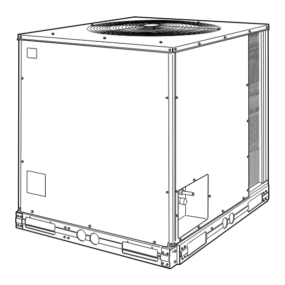
A. Uncrate Unit (See Fig. 1)
Remove unit packaging except for the top skid assembly and
wood bumpers, which should be left in place until after unit
is rigged into place.
B. Inspect Shipment
File claim with shipping company if shipment is damaged or
incomplete.
C. Consider System Requirements
• Consult local building codes and NEC for special installa-
tion requirements.
• Allow sufficient space for airflow clearance, wiring, refrig-
erant piping, and servicing unit. See Fig. 2.
• Locate unit so that outdoor unit airflow is unrestricted on
all sides and above. Refer to Fig. 2.
• Unit may be mounted on a level pad directly on base rails
or mounted on raised pads at support points. See Fig. 2 for
weight distribution based on recommended support points.
• Provide for condensate drainage and defrost water dis-
posal beneath unit.
• Areas with high snowfall may need elevated mounting for
adequate airflow.
NOTE: If vibration isolators are required for a particular in-
stallation, use corner weight information in Fig. 2 to make
proper selection.
Fig. 1 - 575A090 Unit
575A
Size 090
7
1
⁄
Tons
2
II 575A-90-2
12/1/95
Advertisement
Table of Contents

Related Manuals for Bryant 575A


Summary of Contents for Bryant 575A
-
Page 1: Table Of Contents
INSTALLATION The 575A090 unit uses a semi-hermetic compressor. See Table 1 for physical data. Cancels: II 575A-90-1 The 575A090 outdoor unit is approved for use only with the 524A-H090 indoor unit. Use only approved indoor unit. The 575A090 unit is Underwriters’ Laboratories (UL) and UL Canada approved for use with the 524A-H090 indoor unit only. - Page 2 UNIT W/ UNIT W/ ALUMINUM-FIN COPPER-FIN UNIT Std Unit COIL COIL 575A Dim. A Dim. B Dim. A Dim. B 1 -8 1 -5 1 -9 ⁄ 1 -4 ⁄ 540 245 [508.0] [431.8] [546.0] [425] NOTES: 1. Dimensions in [ ] are in millimeters.
-
Page 3: Rig And Mount The Unit
Table 1 — Physical Data UNIT 575A OPERATING WEIGHT (lb) Aluminum Coils (Standard) Copper Coils (Optional) RIGGING WEIGHT (lb) Aluminum Coils (Standard) Copper Coils (Optional) REFRIGERANT* COMPRESSOR Reciprocating, Semi-Hermetic Quantity...Type Quantity Cylinders Speed (rpm) Oil Charge (oz) (ea) OUTDOOR FAN Quantity...rpm... -
Page 4: Complete Refrigerant Piping Connections
4. Complete refrigerant piping from indoor coil to outdoor coil before opening liquid and suction lines at the 575A unit. See Tables 1 and 2 for piping selection data. —4—... - Page 5 A bi- flow type solenoid valve is required. 5. Filter drier must be of the biflow type, suitable for heat pump duty. 6. Internal factory-supplied TXV and bypass check valve not shown.
-
Page 6: Make Electrical Connections
Fig. 6 — Fusible Plug Locations LEGEND TXV — Thermostatic Expansion Valve NOTE: The 8 o’clock position is shown above. Fig. 7 — TXV Sensing Bulb Location IV. MAKE ELECTRICAL CONNECTIONS WARNING: Unit cabinet must have an uninterrupted, unbroken electrical ground to minimize the possibility of personal injury if an electrical fault should occur. - Page 7 VOLTAGE RANGE UNIT NOMINAL VOLTAGE 575A (V-Ph-Hz) 208/230-3-60 460-3-60 LEGEND — Full Load Amps HACR — Heating, Air Conditioning and Refrigeration — Locked Rotor Amps — Minimum Circuit Amps — National Electrical Code — Outdoor Fan Motor — Rated Load Amps NOTES: 1.
-
Page 8: Start-Up
3. Connect thermostat wires to screw terminals of low- voltage connection board. NOTE: 39 VA is available for field-installed accessories. Con- trol power requirement for heat pump outdoor unit is 36 VA (sealed). The factory-supplied control transformer is rated at 75 VA. -
Page 9: Refrigerant Service Ports
Fig. 11 — Cooling Charging Chart — 575A090 B. Oil Charging Allow unit to run for about 20 minutes. Stop unit and check compressor oil level. Add oil only if necessary to bring oil into view in sight glass. See Table 1 for oil charge. Use only ap- proved compressor oil as follows: Suniso 3GS and WF32-150 Do not reuse drained oil or use any oil that has been exposed... -
Page 10: Checking Cooling And Heating Control Operation
CONTROL The high-pressure switch, loss-of-charge switch, and compres- sor overtemperature safety are located in a Cycle-LOC™ cir- cuit that prevents heat pump operation if these safety devices are activated. The lockout system can be reset by adjusting the thermostat to open the contacts (down for heating mode, up for cooling mode) deenergizing the Cycle-LOC circuitry. -
Page 11: Service
SERVICE CAUTION: When servicing unit, shut off all electri- cal power to unit to avoid shock hazard or injury from rotating parts. I. CLEANING Inspect unit interior at the beginning of each cooling season and as operating conditions require. A. Outdoor Coil Inspect coil monthly. -
Page 12: Service
Fig. 16 — Separating Coil Sections II. LUBRICATION A. Compressors Compressor has its own oil supply. Loss of oil due to a leak in the system should be the only reason for adding oil after the system has been in operation. See Start-Up, Oil Charging section. -
Page 13: Troubleshooting Chart
—13—... - Page 14 Copyright 1995 Carrier Corporation CATALOG NO. BDP-3357-502...
-
Page 15: Preliminary Information
I. PRELIMINARY INFORMATION OUTDOOR: MODEL NO. INDOOR: MODEL NO. ADDITIONAL ACCESSORIES B. Pre-Start-Up OUTDOOR UNIT IS THERE ANY SHIPPING DAMAGE? IF SO, WHERE: WILL THIS DAMAGE PREVENT UNIT START-UP? CHECK POWER SUPPLY. DOES IT AGREE WITH UNIT? HAS THE GROUND WIRE BEEN CONNECTED? HAS THE CIRCUIT PROTECTION BEEN SIZED AND INSTALLED PROPERLY? ARE THE POWER WIRES TO THE UNIT SIZED AND INSTALLED PROPERLY? HAVE COMPRESSOR HOLDDOWN BOLTS BEEN LOOSENED (Snubber washers are snug, but not tight)? - Page 16 C. Start-Up CHECK INDOOR-FAN SPEED AND RECORD. CHECK OUTDOOR-FAN SPEED AND RECORD. AFTER AT LEAST 15 MINUTES RUNNING TIME, RECORD THE FOLLOWING MEASUREMENTS: OIL PRESSURE SUCTION PRESSURE SUCTION LINE TEMP DISCHARGE PRESSURE DISCHARGE LINE TEMP ENTERING OUTDOOR-AIR TEMP LEAVING OUTDOOR-AIR TEMP INDOOR ENTERING-AIR DB (dry bulb) TEMP INDOOR ENTERING-AIR WB (wet bulb) TEMP INDOOR LEAVING-AIR DB TEMP...
Need help?
Do you have a question about the 575A and is the answer not in the manual?
Questions and answers