Table of Contents
Advertisement
Quick Links
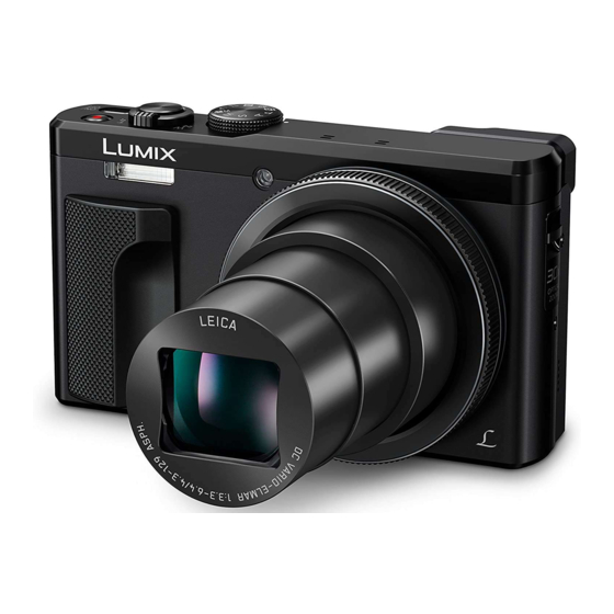
DMC-TZ80EB
Model No.
DMC-TZ80EE
DMC-TZ80EF
DMC-TZ80EG
DMC-TZ80EP
DMC-TZ80GA
DMC-TZ80GC
DMC-TZ80GN
DMC-TZ81EG
DMC-ZS60P
DMC-ZS60PP
DMC-ZS60GH
Colours
Product Color
(S)....................Silver Type (Except GC)
(K)....................Black Type
© Panasonic Corporation 2016.
Unauthorized copying and distribution is a violation
of law.
ORDER NO.DSC1602001CE
B26
Digital Camera
Advertisement
Table of Contents


Need help?
Do you have a question about the DMC-TZ80EB and is the answer not in the manual?
Questions and answers
I wish to replace the battery cover on my TZ80 I have the back cover of but cannot remove the front panel can you assist. I do not want to disassemble the whole camera.