Table of Contents
Advertisement
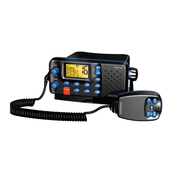
This PLL controlled VHF marine mobile transceiver provides an accurate and stable multi-channel
operation.
The transceiver consists of 12 main sections
Transmitting stage
!" Receiving stage
!" Transmitter Stage
The audio is picked up from the internal Mic. The audio signal is then amplified by Audio Amplifier,
IC205C [NJM3403AM], IC205 B [NJM3403AM] and filtered by a low pass filter IC10C [NJM3403AM]),
IC10D [NJM3403AM]). The audio that is adjusted by VR3 to obtain a suitable RF frequency-deviation,
modulates the carrier of VCO, through Varicap (VD302).
The modulated signal output from the VCO is pre-amplified by Q2, and IC1 (RA35H1516M-01). When the
supply voltage is 13.8V, this signal will be amplified up to 1W or 25W. The signal is filtered by low-pass
filter circuit of which consists of L1, L2, L4, C1, C2, C3, C5, C6. C14, C47 and C62.These low pass filters
are necessary to suppress the second and the third harmonics as higher. The signal is then fed into the
antenna input and radiated out. The signal is also fed into another path consisting of C9, C10, D3, D4 for
sampling, and is converted into a direct current voltage for the Automatic Power Control (APC) circuit
IC12 (NJM2904M) Q5, Q14, Q15,Q24 to control the voltage of IC1 Pin 2 to maintain the output power
stability. Q15 is used control Hi/Lo power
When the unit is transmitting, the channel control voltage is added to the TX VCO varicap VD306. The
capacitance of VD302 is varied following the audio signal, therefore the carrier is modulated to form the
modulated signal.
!" Receiver
The receiver uses a double frequency super-heterodyne circuit. The first Immediate Frequency (IF) is
21.4 MHz and the second is 455 KHz.
The RF signal is received by the antenna, and passes through a low-pass filter network L1, L2, L3, L9, C1,
C2, C3, C5, C6. C14, C47 and C62 to filter out unwanted signal. the received RF signal then passes
through a high RF transformer L10 and is amplified by RF amplifier Q9. L11, L12, L13, C15, C18, C20
form the band pass filter. The RF signal then is mixed with the local oscillation frequency by the mixer
THEORY OF OPERATION
VHF7100/VHF7000 (For NAVMAN)
November 28, 2003
(only VHF7100EC)
[only VHF7100USA]
[only VHF7000ROW without]
[only VHF7000ROW without]
(only VHF7100EC)
TEKCOM Industries Limited
Page 1 of 6
Advertisement
Table of Contents

Subscribe to Our Youtube Channel
Related Manuals for Navman VHF7100


Summary of Contents for Navman VHF7100
- Page 1 THEORY OF OPERATION VHF7100/VHF7000 (For NAVMAN) November 28, 2003 This PLL controlled VHF marine mobile transceiver provides an accurate and stable multi-channel operation. The transceiver consists of 12 main sections Transmitting stage !" Receiving stage !" Local oscillator PLL (Phase Lock Loop) Circuit !"...
- Page 2 D22, D23. The first IF (Immediate Frequency) 21.4 MHz is produced. This IF is passed through a coil T2 and a pair of crystal filter F1, F2 to further filter out other unwanted signals. The first IF then is amplified by Q11 and the IF amplifier IC7 (BA4116FN).
- Page 3 IC6D low-pass filter form FSK signal. This FSK is signal decoded by IC609. The DSC is restored by IC203 [MCU] with RX data from IC9 pin7. While the VHF7100 EC While the VHF7100 EC , DSC signal is from 2nd receiver. It be Send to IC15 pin13 on the main PCB. !" ATIS Feature ATIS encoded by MCU IC203, through RP1, R237, R234, produces D/A conversion, and IC205D low pass filter forms FSK signal.
- Page 4 ALIGNMENT AND ADJUSTMENT This transceiver is completely aligned at the factory and does not require any adjustments for installation. However it is considered as good practice to verify that none of the adjustments are changed. Do not adjust any circuitry in this radiotelephone unless you understand the circuit operation and have experience in adjusting radiotelephone.
- Page 5 TROUBLE SHOOTING Before troubleshooting, prepare your unit as follows: !" Turn volume control fully clockwise so that it is all the way up. !" Install the batteries onto your unit. Item Symptom Cause/Remedy !" Check the power voltage and power switch. Unit is not able to turn on.
- Page 6 DISASSEMBLY INSTRUCTIONS Rotate counterclockwise volume knob to OFF position. Pull out all external wires (GPS, SP, POWER). Unscrew 2 mounting nuts. Remove the main radio from the mounting bracket. Unscrew the four screws of hand MIC. Separate the front cabinet and bottom cabinet of the hand MIC. Unscrew 6 screws for the bottom cabinet of the main unit.
Need help?
Do you have a question about the VHF7100 and is the answer not in the manual?
Questions and answers