Advertisement
Quick Links
Advertisement

Related Manuals for FM Systems SDI MASTER


Summary of Contents for FM Systems SDI MASTER
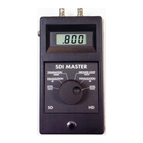
- Page 1 SDI-1 SDI MASTER INSTRUCTION BOOK IB-6374-01 ALL RIGHTS RESERVED...
- Page 2 SDI MASTER TABLE OF CONTENTS 1.0 SHIPPING INSPECTION. 1.1 DESCRIPTION. 2.0 DIGITAL TELEVISION DATA SIGNALS THIS METER WILL MEASURE. 3.0 HOW TO MEASURE SIGNAL STRENGTH ON (SD) TELEVISION SIGNALS. 4.0 MEASURE THE FREQUENCY RESPONSE EQUALIZATION ON SD TV SIGNALS. 5.0 HOW TO MEASURE SIGNAL STRENGTH OF HD TELEVISION SIGNALS.
- Page 3 SHIPPING INSPECTION Remove the unit from the shipping container and inspect for shipping damage. If any damage is found contact the shipping carrier for further instructions. The SDI-1 is shipped fully tested and ready for use. You should have the SDI-1 meter with a 9V battery in the battery compartment, (Note the battery will not be attached to the snap-on battery clip for shipping reasons).
- Page 4 Disconnect the coaxial cable from the receiving data terminal. Connect the coaxial cable to be measured to the input coaxial connector marked (INPUT) on the SDI MASTER. Connecting the SDI MASTER to a distribution amplifier that in turn is connected to the cable is OK, IF the distribution amplifier does not correct frequency response or amplify the signal in any way (as some distribution amplifiers do).
- Page 5 Disconnect the coaxial cable from the receiving data terminal. Connect the coaxial cable to be measured to the "INPUT" coaxial connecter on the SDI MASTER. Rotate the selector switch on the SDI MASTER to HD LEVEL (on the right hand side of the switch), and depress and hold down the button on the bottom of the meter to observe the meter reading.
- Page 6 Connect a short patch cord (about one foot long) from the BNC connector labeled "LOAD" on the SDI MASTER to the input of the data receiver to be tested. Rotate the selector switch on the SDI MASTER to TERMINATION, and depress and hold the power button to read the termination value. This meter can read any value of termination from 000.0 to 199.9 Ohms with an accuracy of +/- 0.1 Ohms.
- Page 7 If the source is terminated to the same impedance as the characteristic impedance of the coaxial cable, no secondary reflection can occur. However, if the sending-end termination is not exactly correct, or if there are other discontinuities in the cable that would cause reflections, then data being carried by these reflection will interfere with the data being received and data errors could result.
- Page 8 The formula for calculating the Return Loss created by any discontinuity in a 75 Ohm transmission system follows: Zt - Zo Zt = Terminating impedance Return Loss = 20 log ------------------ Zt + Zo Zo= Cable characteristic impedance = 75 Ohms TERMINATION RETURN-LOSS TABLE 2 TERMINATION 75 OHM TERMINATION...
-
Page 9: Care And Maintenance
SDI MASTER, then connect the receiving data terminal to the "LOAD" coaxial connector on the SDI MASTER, rotate the front selector knob to the "GROUND LOOP" position, then depress and hold down the power button until the test is completed. The result will be displayed on the LCD. -
Page 10: Auxiliary Equipment
If all the decimal points turn on during use, replace the 9Volt battery with a fresh battery immediately. Be aware that a dead battery can read 9VDC on a Voltmeter, if the battery is not under load. To correctly measure the battery Voltage, leave it connected to the load (SDI-1) and turn on the SDI-1 while reading the Voltmeter with the "load on".
Need help?
Do you have a question about the SDI MASTER and is the answer not in the manual?
Questions and answers