
Related Manuals for FM Systems CAMERA MASTER II


Summary of Contents for FM Systems CAMERA MASTER II
- Page 1 CM-2 CAMERA MASTER II OPERATORS MANUAL IB 6367-03 COPYRIGHT ALL RIGHTS RESERVED 2-10-2006...
-
Page 2: Table Of Contents
CM-2 CAMERA MASTER II PAGE DESCRIPTION HOW TO MEASURE VIDEO SIGNALS HOW TO MEASURE CCTV CAMERA LEVELS MANUAL IRIS CCTV CAMERA AUTOMATIC IRIS CCTV CAMERA MULTI-CAMERA SWITCHED MONITOR SYSTEMS COAXIAL CABLE CONTINUITY MEASUREMENT HOW TO SET BACK FOCUS CABLE SLOPE EQUALIZATION MEASUREMENT... -
Page 3: Description
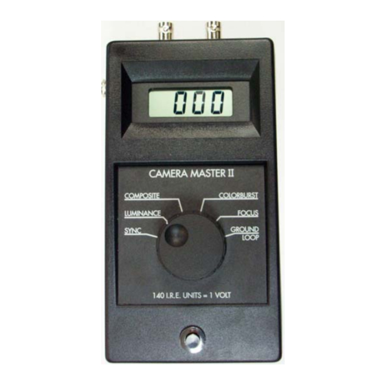
DESCRIPTION The CM-2 Camera Master measures six attributes of a camera video signal: SYNC measures amplitude video synchronizing pulse and can be used to check for correct video level, coaxial cable continuity and correct termination impedance. LUMINANCE measures the "white level" of the video, it is used to adjust the camera IRIS to the correct setting for the existing lighting conditions. -
Page 4: How To Measure Cctv Camera Levels
Two BNC coaxial connectors are provided, which are connected directly together inside case. input internally terminated and so it is a very high impedance input. This assures that the video signal will not be reduced in amplitude when the meter is connected to the circuit to be measured. -
Page 5: Multi-Camera Switched Monitor Systems
one BNC connector on the CM-2 with a short coaxial patch cord. Connect the coaxial cable linking the camera to the monitor center to the other BNC connector or place a 75 Ohm termination onto the other BNC connector. NOTE: The camera must be terminated with 75 Ohms, either at the meter or at the far end of the coaxial cable to obtain correct level... -
Page 6: Cable Slope Equalization Measurement
The "Back Focus" adjustment on a camera is best set on a test bench after the lens that is to be used has been installed. Place the camera a known distance from a test pattern card or other picture that contains high contrast and detailed image. Make sure that the card fills the camera field of view and is perpendicular to the pointing direction of the camera. -
Page 7: Care And Maintenance
measure ground loop readings camera switch selector to “GROUND LOOP” and connect the cable coming from the monitor equipment to either BNC connector on the CM-2. Then connect a short cable to the camera output. Then take the loose end of the short cable and touch the outer shield (the metal outside portion) of the connector to the ¼... -
Page 8: Charger
Readings should not be taken if LCD display is flashing, the battery must be replaced by a fresh 9 Volt battery. Special circuitry prevents incorrect meter reading under low battery conditions by preventing instrument turn-on when the battery is discharged. The battery is located in the case, under the digital meter, with access provided by a sliding plastic cover plate that has the word OPEN printed on it. - Page 9 Someone once said "Knowledge is the key to success". This rule also applies to the installation and maintenance of CCTV camera equipment. Have you ever installed a CCTV camera system and then had back solve problem that overlooked? basic understanding of CCTV video signals, can save you hundreds of man hours, improve customer relations and increase job profitability all at the same time.
- Page 10 A quick measurement of the peak to peak video signal will re-assure you that the CCTV camera is putting out the right level. The standard level is 140 I.R.E. units on the “COMPOSITE” scale. COLOR CAMERA'S AND WHAT IS COLOR BURST ANYWAY? More color cameras are being used in CCTV installations.
Need help?
Do you have a question about the CAMERA MASTER II and is the answer not in the manual?
Questions and answers