
Related Manuals for Skyworth SMVH24A-5C1A3NG


Summary of Contents for Skyworth SMVH24A-5C1A3NG
- Page 1 MODEL SMVH09A-2C1A3NG SMVH12A-3C1A3NG SMVH18A-4C1A3NG SMVH24A-5C1A3NG (Refrigerant R32)
- Page 2 CONTENT 1. Summary and Features ................1 2. Safety Precautions ..................3 ....................5 ..................... 5 3.2 Operation Characteristic Curve ................9 3.3 Capacity Variation Ratio According to Temperature ..........9 3.4 Cooling and Heating Data Sheet in Rated Frequency ......... 10 3.5 Noise Curve ......................
- Page 3 ..................62 9.1 Error Code List ......................62 ................65 10. Removal Procedure ................82 10.1 Removal Procedure of Indoor Unit ............... 82 10.2 Removal Procedure of Outdoor Unit ..............86...
- Page 4 Indoor unit Outdoor unit Power Supply Power Supply Intake SMVH09A-2C1A3NG KEB001Z2100 SMVH09A-2C1A3NG(I) SMVH09B-2A2A3NG(O) SMVH12A-3C1A3NG KEB001Z2090 SMVH12A-3C1A3NG(I) SMVH12B-3A2A3NG(O) 220-240V~, Outdoor Unit SMVH18A-4C1A3NG KEB001Z2080 SMVH18A-4C1A3NG(I) SMVH18B-4A2A3NG(O) 50Hz,1Ph SMVH24A-5C1A3NG KEB001Z2110 SMVH24A-5C1A3NG(I) SMVH24B-5A2A3NG(O) Indoor Unit SMVH09A-2C1A3NG(I) SMVH12A-3C1A3NG(I) SMVH18A-4C1A3NG(I) SMVH24A-5C1A3NG(I) Outdoor Unit SMVH09B-2A2A3NG(O) SMVH12B-3A2A3NG(O) Remote Controller...
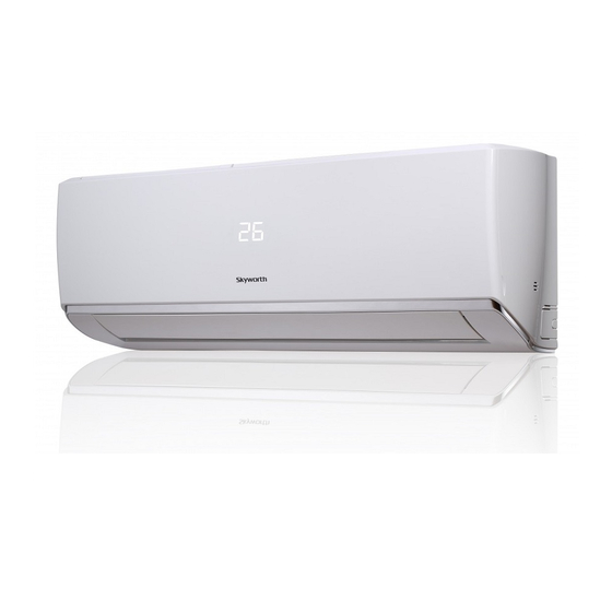
- Page 5 Summary and Features Outdoor Unit SMVH18B-4A2A3NG(O) SMVH24B-5A2A3NG(O)
- Page 6 Safety Precautions 2. Safety Precautions Installing, starting up, and servicing air conditioner can be hazardous due to system pressure, electrical components, and equipment.Untrained personnel can perform basic maintenance functions such as cleaning coils. All other operations should be performed by trained service personnel.When handling the equipment, observe precautions in the manual and on tags, stickers, and labels attached to the equipment.
- Page 7 Safety Precautions Please read this operating manual carefully before operating the unit. The Refrigerant To realize the function of the air conditioner unit, a special refrigerant circulates in the system.The used refrigerant is the fluoride Compared to common refrigerants, R32 is a nonpolluting refrigerant with no harm to the ozonosphere.The influence upon the WARNING: Do not use means to accelerate the defrosting process or to clean, other than those recommended by the manufacture.Should repair be necessary, contact your nearest authorized Service Center.
- Page 8 Parameter Unit Value Model SMVH09A-2C1A3NG SMVH12A-3C1A3NG Product Code KEB001Z2100 KEB001Z2090 Rated Voltage 220-240 220-240 Power Rated Frequency Supply Phases Power Supply Mode outdoor outdoor Cross-sectional Area of Power Cable Conductor Recommended Power Cable(Core) 198/264 198/264 Cooling Capacity 2600 3500 Min. Cooling Capacity 3300 4000 Pdesignc...
- Page 9 Outdoor Unit Model SMVH09B-2A2A3NG(O) SMVH12B-3A2A3NG(O) Compressor Trademark panasonic panasonic panasonic Wanbao Appliances panasonic Wanbao Appliances Compressor Manufacturer Compressor(guangzhou) Compressor(guangzhou) CO.,LTD./panasonic CO.,LTD./panasonic Compressor Model 9RS092ZAB21 9RS102ZAA21 Compressor Oil FV50S FV50S Compressor Type Rotary Rotary Compressor LRA. 20.2 16.5 Compressor RLA 6.22 6.48 Compressor Power Input Compressor Overload Protector...
- Page 10 Parameter Unit Value Model SMVH18A-4C1A3NG SMVH24A-5C1A3NG Product Code KEB001Z1550/KEB001Z2080 KEB001Z1560/KEB001Z2110 Rated Voltage 220-240 220-240 Power Rated Frequency Supply Phases Power Supply Mode outdoor outdoor Cross-sectional Area of Power Cable Conductor Recommended Power Cable(Core) 198/264 198/264 Cooling Capacity 5270 6450 Min. Cooling Capacity...
- Page 11 Outdoor Unit Model SMVH18B-4A2A3NG(O) SMVH24B-5A2A3NG(O) Compressor Trademark panasonic panasonic panasonic Wanbao Appliances panasonic Wanbao Appliances Compressor Manufacturer Compressor(guangzhou) Compressor(guangzhou) CO.,LTD./panasonic CO.,LTD./panasonic Compressor Model 9RD132ZEA21 9RD160ZAA21 Compressor Oil FV50S FV50S Compressor Type Rotary Rotary Compressor LRA. Compressor RLA Compressor Power Input 1260 1645 Compressor Overload Protector...
- Page 12 3.2 Operation Characteristic Curve Cooling Heating Condition Condition Indoor:DB 20°C Indoor:DB 27°C WB19°C Indoor air flow: Super High Indoor air flow: Super High Pipe length:5m Pipe length:5m Voltage:230V Voltage:230V Compressor Speed(rps) Compressor Speed(rps) 3.3 Capacity Variation Ratio According to Temperature Heating operation ambient temperature range is -20ºC~24ºC Cooling Heating...
- Page 13 3.4 Cooling and Heating Data Sheet in Rated Frequency Pressure of gas pipe Inlet and outlet pipe Rated cooling Fan speed of connecting indoor and temperature of heat Outdoor fan Model condition(°C) (DB/WB) indoor unit outdoor unit mode (rpm) Indoor Outdoor P (MPa) T1 (°C)
- Page 14 Function and Control 4. Function and Control 4.1 Remote Controller Operations Set fan speed I feel Wi-Fi signal Turbo mode Quiet mode Auto mode Clean mode Cooling mode Health function Dry mode ECO mode Fan mode Sleep mode Heating mode Child lock Left&right swing Clock display...
- Page 15 Function and Control Press this button can turn on or turn off the air conditioner. Press this button to select your required operation mode. Auto Cool Heat setting. Set temperature can’t be adjusted and will not be displayed as well. Press "FAN" button can adjust fan speed. Press " "...
- Page 16 Function and Control When selecting " " with remote controller, it’s auto swing. left&right swing louver of air conditioner will swing left&right When selecting " Left&right swing louver of air conditioner will stop at that position as shown by the icon to swing. When selecting "...
- Page 17 Function and Control This button can set the time for timer on. After pressing this button, " " icon disappears, "ON" and " " icon on remote controller blinks. Press "+" or "- "button within 5s to set "TIMER ON" time. Each pressing of "+" or "-" button, the time will increase or decrease 1 hour.
- Page 18 Function and Control Timing defrost In the heating mode, press "SLEEP" and "TURBO" buttons together for 3s would start or cancel the Timing defrost. The minimum cooling temperature setting In the off mode,pressing "TEMP"and "-" button at the same time,the LCD will display the minimum cooling temperature.The default temperature is 16°C and you can adjust the temperature with "+"...
- Page 19 Function and Control 4.2 Smart APP User Guide 4.2.1 Download the Easy Home AMS Application(Referrer to as APP hereinafter) Search "Easy Home AMS" to download Andriod version APP from Google Play and search "Easy Home AMS" to download IOS version APP from App Store. 4.2.2 Production Introduction Easy Home air conditioner is functioning based on the built-in smart module SWM100 through the Wi-Fi network, that the mobile phones or other mobile devices can be connected to the Easy Home air conditioner to monitor and control the air...
- Page 20 Function and Control Click to choose air conditioner on the list. 21:09 21:09 21:09 Search for air conditioners Search for air conditioners Search for air conditioners Notice: Air conditioner hotspot name and password of the indoor unit. Hot spot Name: SkySAC _XXXX Wait for connecting...14 Hot spot Password: 88888888 Refresh...
- Page 21 Connecting Air Conditioner Available Networks... Available Networks Available Networks Family-ac04 Network Family-ac04 Family-ac04 SkySAC-EADF Please Input the password of skyworth-ac04 Click Switch Button and connecting the Cancel Net t wor w k Family-ac04 Switch Switch space return I. Click to change network.
- Page 22 Function and Control 4.2.6 Search the air conditioner in Wireless Local Area Network (WLAN) If the air conditioner has already connected to the WLAN, a new mobile phone users that connected with same WLAN can search the air conditioner through the APP. Enter the APP and select "Add AC" from the menu, and enter the page as shown in Yes", the APP will automatically search for the air-conditioner under same WLAN.
- Page 23 Function and Control (1 )Requirement for use Notice: Please connect the router to the Internet when it required. (2) If cannot control air conditioner by APP phone. (3) Diagram of communication The path of communication between mobile phone and air conditioner: Figure 8.1 to achieve the connection.
- Page 24 When the indication light is turned off: Wi-Fi light gets off, the Wi-Fi function can still be controlled. (13 )What is the applicable range for Skyworth Air Conditioner Wi-Fi module? This module is only applicable to Skyworth Air conditioner. (14) Disconnected frequently Please check if there are more than 2 sets of mobile devices connected via the same Wi-Fi router to control the air conditioner.
- Page 25 Function and Control 4.3 Description of Each Control Operation (1) Auto (2) Cooling (3) Dehumidifying (4) Air fan (5) Heating 4.3.2 Control Indoor fan(Quiet、speed 1、speed 2、speed 3、speed 4、speed 5、Turbo), left and right louver, up and down louver, buzzer, display, outdoor electric heater(option), outdoor power, healthy(option). 4.3.3 Basis control function Cooling mode (1) Setting Temp 16-31 degree,the indoor fan and louver run as the original mode.
- Page 26 Function and Control 4.3.6 Other Function when you press this button,it will enter auto mode,indoor motor in auto fan speed,Indoor fan run and louver motor stop. Press the auto button,unit will be off. (2) Filter cleaning (3) Health Indoor healthy function start when push healthy button. (4) Dry Unit will run in cooling 10 min after set up dry function.
- Page 27 n tallation anual 5. Installation Manual All the work men who are engaging in the refrigeration system should bear thevalid certification awarded by the authoritative refrigerant.It can only be repaired by the method suggested by the equipment’s manufacturer. 5.1.2 Installation notes 2.It is not allowed to drill hole or burn the connection pipe.
- Page 28 n tallation anual 5.1.6 Installation prepare WARNING — Any presence of air or other foreign substance in the refrigerant circuit will cause system pressure rise or compressor rupture, resulting in injury. 2. When installing or moving this unit, do not charge the refrigerant which is not comply with that on the nameplate or —...
- Page 29 n tallation anual 5.1.1 Installation Site Instructions Installing the unit in the following places maycause malfunction. If it is unavoidable, please consult the local dealer: 2.The place with high-frequency devices (such as welding machine,medical equipment). 3.The place near coast area. 4.The place with oil or fumes in the air.
- Page 30 n tallation anual 5.3 Installation Dimension Diagram Space to the wall At least 15cm At least 15cm Space to the wall Drainage pipe...
- Page 31 n tallation anual 5.4 Installation Indoor Unit Step 1: Choosing installation location Step 2: Install wall-mounting frame holes on the wall . Step 3: Open piping hole 1. Choose the position of piping hole according to the direction of outlet pipe. The position of piping hole should be a little lower than the wall-mounted frame, shown as below.
- Page 32 n tallation anual Step 5: Connect the pipe of indoor unit 1. Aim the pipe joint at the corresponding bellmouth. pipe pipe joint union nut 2. Pretightening the union nut with hand. 3. Adjust the torque force by referring to the following sheet. Place the open-end wrench on the pipe joint and place the torque wrench on the open-end union nut.
- Page 33 n tallation anual Step 7: Connect wire of indoor unit 1. Open the panel, remove the screw on the wiring cover and then take down the cover. panel N(1) blue black brown yellow- green Outdoor unit connection screw wiring cover 2.
- Page 34 n tallation anual 5.5 Installation Outdoor Unit Step 1: Fix the support of outdoor Select it according to the actual installation situation 1. Select installation location according to the house structure. Note: to install drain joint. screws are needed; for the unit with cooling capacity of 10000W~16000W, at least 3cm above Step 2: Install drain joint (Only for cooling and heating unit)
- Page 35 n tallation anual Step 5: Connect indoor and outdoor pipe 1. Remove the wire clip; connect the power connection wire and signal control wire (only for cooling and heating unit) to the N(1) yellow- yellow- blue brown blue black brown green green Indoor unit connection...
- Page 36 n tallation anual Step 7: Vacuum pumping Use vacuum pump 1. Remove the valve caps on the liquid valve and gas valve and liquid valve piezometer the nut of refrigerant charging vent. gas valve 2. Connect the charging hose of piezometer to the refrigerant refrigerant charging valve cap charging vent of gas valve and then connect the other charging...
- Page 37 n tallation anual 5.6 Check after installation The unit may drop, shake or emit noise Have you done the refrigerant leakage test? capacity. It may cause condensation and water dripping. Is water drained well? It may cause condensation and water dripping. Is the voltage of power supply according to the voltage marked on the It may cause malfunction or damaging the parts.
- Page 38 n tallation anual 1. Standard length of connection pipe 2. Min. length of connection pipe is 3m. Cooling capacity Cooling capacity of connection pipe difference of connection pipe difference 5000Btu/h(1465W) 24000Btu/h(7032W) 7000Btu/h(2051W) 28000Btu/h(8204W) 9000Btu/h(2637W) 36000Btu/h(10548W) 12000Btu/h(3516W) 42000Btu/h(12306W) 18000Btu/h(5274W) 48000Btu/h(14064W) 4. The additional refrigerant oil and refrigerant charging required after prolonging connection pipe for each additional 5m of connection pipe.
- Page 39 n tallation anual 5.9 Pipe expanding method A: Cut the pipe pipe pipe cutter leaning uneven burr Remove the burrs with shaper and prevent the burrs from getting into the pipe. pipe downwards shaper D: Put on the union nut Remove the union nut on the indoor connection pipe and outdoor valve;...
- Page 40 Con truction i 6. Construction Views 6.1 Indoor Unit Unit:mm Model W(mm) H(mm) D(mm) 1003 1109 ● 09K Φ55 Φ55 ● 12K Φ55 Φ55...
- Page 41 Con truction i ● 18K 1003 Φ55 Φ55 ● 24K 1109 Φ55 Φ55 Unit:mm...
- Page 42 Con truction i 6.2 Outdoor Unit Model: SMVH09B-2A2A3NG(O) , SMVH12B-3A2A3NG(O) Model: SMVH18B-4A2A3NG(O)
- Page 43 Con truction i Model: SMVH24B-5A2A3NG(O) Unit:mm...
- Page 44 lod d i and art 7. Exploded Views and Parts List 7.1 Indoor Unit Model:SMVH09A-2C1A3NG(I)
- Page 45 lod d i and art Part Code Description SMVH09A-2C1A3NG(I) Product Code KEB001N2100 Panel K20000021T Filter Subassembly K15420004 Air Outlet K1126000201D Flannelette Strip K15810015 Flannelette Strip K15810017 Panel K20000113 Left Side Plate K21420003 K15210001 Air Louver K15200039 Swing Louver 1 K15200004 Chassis Subassembly K21400028 Water Pan Rubber...
- Page 46 lod d i and art Model: SMVH12A-3C1A3NG(I)
- Page 47 lod d i and art Part Code Description SMVH12A-3C1A3NG(I) Product Code KEB001N2090 Panel K20000022T Filter Subassembly K15420003 Air Outlet K11260001D Flannelette K15810040 Flannelette Strip K15810015 Left Side Plate K21420002 Panel K20000003 K15210001 Air Louver K15200001 Swing Louver 1 K15200002 Chassis Subassembly K21400002 Water Pan Rubber K62600006...
- Page 48 lod d i and art Model: SMVH18A-4C1A3NG(I) 14 15...
- Page 49 lod d i and art Part Code Description SMVH18A-4C1A3NG(I) Product Code KEB001N2080 Panel K20000019T Screw Cap K21830003 Filter Subassembly K15420006 Air Outlet K1126000301D Flannelette Strip 1 K15810045 Flannelette Strip 2 K15810043 Left Side Plate K21420005 Panel K2000001001 K15210001 Air Louver K15200008 Swing Louver K15200007...
- Page 50 Model: SMVH24A-5C1A3NG(I)
- Page 51 Part Code Description SMVH24A-5C1A3NG(I) Product Code KEB001N2110 Panel K11010006T Screw Cap K21830005 Filter Subassembly K15420012 Air Outlet K11260011D Left Side Plate K21420013 Panel K20000026 K15210001 Air Louver K15200016 Swing Louver K15200015 Chassis Subassembly K21400013 Water Pan Rubber...
- Page 52 lod d i and art 7.2 Outdoor Unit Model: SMVH09B-2A2A3NG(O) ,SMVH12B-3A2A3NG(O) 25 24...
- Page 53 lod d i and art Part Code Description SMVH09B-2A2A3NG(O) SMVH12B-3A2A3NG(O) Product Code KEB001W1530 KEB001W1540 Grill K21600001 K21600001 K15010001 K15010001 Motor K16800008 K16800008 Front Panel K11010001P K11010001P Left Side Panel K10600067 K10600067 Motor Support K1120002802 K11200028 Top Cover K10450004P K10450004P Partition Board Subassembly K10440035 K10440035 Condenser Assembly...
- Page 54 lod d i and art Model: SMVH18B-4A2A3NG(O)
- Page 55 lod d i and art Part Code Description SMVH18B-4A2A3NG(O) Product Code KEB001W1550 Grill K21600005 K15010005 Fan Motor K16800028 Front Panel K11010007P Chassis Subassembly K11034018P Small Handle K22210004 Left Side Panel K10600031P Motor Support Subassembly K1120001703 Top Cover K10450034P Partition Board Subassembly K10440028 Condenser Subassembly K20207004...
- Page 56 lod d i and art Model: SMVH24B-5A2A3NG(O)
- Page 57 Exploded Views and Parts List Part Code Description SMVH24B-5A2A3NG(O) Product Code KEB001W1560 Grill K21600002 K15010002 Front Panel K11010002P Odu Fan Motor K16800015 Motor Support Subassembly K11200015 Left Side Panel K10600005P Small Handle K22210004 Partition Board Subassembly K10440015 Top Cover K10450010P Support Panel K10620002 Condenser Assembly...
- Page 58 e ati ia ra 8. Schematic Diagram 8.1 Electrical Wiring Meaning of marks Symbol YEGN Color symbol ORANGE WHITE YELLOW YELLOW GREEN BROWN BLUE BLACK VIOLET Symbol COMP. 4WAY Name COMPRESSOR 4-WAY VALVE ELECTRONIC EXPANSION VALVE PROTECTIVE EARTH ◆ Indoor Unit...
- Page 59 e ati ia ra ◆ Outdoor Unit Model: SMVH09B-2A2A3NG(O) , SMVH12B-3A2A3NG(O),SMVH18B-4A2A3NG(O) COMP Please don’t touch any electronic component or terminal when the machine is running,stopping or has been powered off for less than 30 minutes to prevent the risk of electric shock! K51000061 Model: SMVH24B-5A2A3NG(O) COMP...
- Page 60 e ati ia ra 8.2 PCB Printed Diagram 8.2.1 Indoor Unit TOP VIEW Function Auxiliary heating zero wire connector Cold plasma zero wire connector Power supply zero wire connector 4 AC motor connector wire connector AC motor feedback connector Up and down louver motor connector Left and right louver motor connector...
- Page 61 e ati ia ra 8.2.2 Outdoor Unit Model:SMVH09B-2A2A3NG(O), SMVH12B-3A2A3NG(O), SMVH18B-4A2A3NG(O) ● Top View NO. Silk scren name Connector Function note U(BU), Compressor interface Used to connect the compressor: U (BU) - (YE) - yellow blue, V, W (RD) - red V(YE),W(RD) Overload interface Used to connect the compressor overload protector, the two white lines.
- Page 62 e ati ia ra ● Bottom View Name Compressor control circuit Compressor phase current sampling circuit & PFC current sampling circuit Power factor correction (PFC) control circuit Master control chip circuit DC fan electric circuit, sampling circuit Switch power supply circuit Wire communication circuit Fan and load control circuit...
- Page 63 e ati ia ra Model: SMVH24B-5A2A3NG(O) NO. Silk scren name Connector Function note U(BU), Compressor interface Used to connect the compressor: U (BU) - (YE) - yellow blue, V, W (RD) - red V(YE),W(RD) Overload interface Used to connect the compressor overload protector, the two white lines. Random selection TEMP Temp.sensor interface OFAN,OFAN1 Fan interface...
- Page 64 e ati ia ra Name Compressor control circuit Compressor phase current sampling circuit & PFC current sampling circuit Power factor correction (PFC) control circuit Master control chip circuit DC fan electric circuit, sampling circuit Switch power supply circuit Wire communication circuit Fan and load control circuit...
- Page 65 les ootin 9.1 Error Code List Way of display By remote control Error Name of malfunction and By remote procedure within Error Possible Causes Solution Display conrol compressor stop Type Code status directly procedure 200s or direcly only after compressor stop 200s Filter cleaning reminder Indoor Filter may have dust...
- Page 66 les ootin Compressor phase Outdoor See Diagram 6 See Diagram 6 current peak protection Compressor phase Outdoor See Diagram 7 See Diagram 7 current RMS protection IPM protection Outdoor See Diagram 8 See Diagram 8 1. Check the radiator 1. The radiator ventilation is ventilation is normal abnormal 2.
- Page 67 les ootin 1. Check the outdoor unit 1. The outdoor unit valve is valve is open. close. 2. The refrigerant connecting 2. The refrigerant connecting pipe installation errors. pipe installation errors. 3. Check the inside and Indoor and outdoor 3. The inside and outside Outdoor outside the machine the machine connecting...
- Page 68 les ootin Diagram 1: E0 Start System Abnormal System Problem problem (Such: Stop etc) solved Solutions Outdoor motor abnormal speed Resolve rotate Problem speed problem (Under Cooling mode) solved Outdoor Resolve air abnormal intake Problem inlet problem (Under Cooling mode) solved The system is normal, but the compressor exhaust...
- Page 69 les ootin Diagram 2: Main test points: Overload Anti-high temperature protection Normal protection,please Is the outdoor unit environment improve the indoor and temperature over the 53℃or not? outdoor unit temperature environment before use Indoor and outdoor unit Improve the heat radiation heat radiating is poor.
- Page 70 les ootin Diagram 3: Main test points: After power cut for 20 mins Overload protector SAT is connected. Use ohmmeter measuring the overload protector resistance at ambient temp. <1000 Ω resistance Good reference The electronic terminals circuit diagram expansion FA in good condition line connected Check the electronic expansion valve coil is installed on the...
- Page 71 les ootin Diagram 4: Main test points: Step out during the Step out problem happen operation after power on Check the Check the fan terminals Change fan motor Check the outside fan compressor stop capacity C1 motor is normal. OFAN is connected. more than 3 mins Change outside Improve heat dissipation for...
- Page 72 les ootin Diagram 5: Main test points: Power on the unit Is stop time of the Restart it up after 3 minutes compressor longer than 3 minutes? Refer to the Electrical Wiring Diagram Are the wires for the and check if the connection between compressor connected correctly? Is AP1 and COMP is loose and if the connection sequence right?
- Page 73 les ootin Diagram 6 , 7, 8: Main check points: Fault diagnosis process: Energize and switch on Use AC voltmeter If the voltage Check the supply to measure the IPM protection between terminal L voltage and voltage between occurs after the and N on wiring board XT terminal L and N machine has run for...
- Page 74 les ootin Diagram 9: Main detection points: ● Is there jumper cap on the main board? ● Is the jumper cap inserted correctly and tightly? ● The jumper is broken? ● The motor is broken? Malfunction diagnosis process: Start Is there jumper cap on the mainboard? Assemble the jumper cap with the same model Is malfunction...
- Page 75 les ootin Diagram 10: Malfunction of Blocked Protection of IDU Fan Motor L2 Main detection points: ● SmoothlyIs the control terminal of PG motor connected tightly? ● SmoothlyIs the feedback interface of PG motor connected tightly? ● The fan motor can't operate? ●...
- Page 76 les ootin Diagram 11: Main check points: Check the indoor unit main board communication circuit and outdoor unit main board communication circuit (AP1)are in good condition. Start The unit operating normal before the fault been found Check the indoor and outdoor unit connection status by control circuit diagram Check the connection wire from...
- Page 77 les ootin Diagram 12: Outdoor unit communication circuit detection process as follows ( outdoor unit key test points) Start Use the Tesr 10 position to test voltage values by voltmeter Numerical change Use the Tesr 13 position to test voltage values by voltmeter Numerical change Outdoor unit error...
- Page 78 les ootin Diagram 13: P7 Troubleshooting Start The power supply voltage The normal nameplate voltage Error declared is not stable with volatility. rated wiithin 10% range The power supply voltage Adjust the power supply voltage, ensure Error declared is low and overload. that the voltage keep in normal range Make sure indoor and Clean the...
- Page 79 les ootin Diagram 14: Power factor correct (PFC) fault P9 (a fault of outdoor unit) (AP1 here in after refers to the control board of the outdoor unit) Mainly detect: Fault diagnosis process: Start Check wiring of the reactor (L) of the outdoor unit and the PFC capacitor Replace it as per the...
- Page 80 les ootin 1. Air Conditioner Can't be Started Up Possible Causes Discriminating Method (Air conditioner Status) Troubleshooting No power supply, or poor After energization, operation indicator isn’t bright yes,wait for power recovery. If not, check power connection for power plug and the buzzer can't give out sound supply circuit and make sure the power plug is connected well.
- Page 81 les ootin 4. ODU Fan Motor Can't Operate Possible Causes Discriminating Method (Air conditioner Status) Troubleshooting Connect wires according to wiring diagram to Wrong wire connection, or poor Check the wiring status according to circuit make sure all wiring terminals are connected connection diagram Measure the capacity of fan capacitor with an...
- Page 82 les ootin Temp.( Temp.( Temp.( Temp.( 22.53 4.986 1.451 138.1 21.51 4.802 1.408 128.6 20.54 4.625 1.363 121.6 19.63 4.456 1.322 18.75 4.294 1.282 108.7 17.93 4.139 1.244 102.9 17.14 3.99 1.207 97.4 16.39 3.848 1.171 92.22 15.68 3.711 1.136 87.35 3.579 1.103...
- Page 83 les ootin Temp.( Temp.( Temp.( Temp.( 361.8 48.42 9.803 2.663 339.8 46.11 9.42 2.577 319.2 43.92 9.054 2.495 41.84 8.705 2.415 282.2 39.87 8.37 2.339 265.5 38.01 8.051 2.265 249.9 36.24 7.745 2.194 235.3 34.57 7.453 2.125 221.6 32.98 7.173 2.059 208.9 31.47...
- Page 84 les ootin Appendix 3: Resistance Table for Indoor and Outdoor Ambient Temperature Sensors (50K) Temp. Resistance Temp. Resistance Temp. Resistance Temp. Resistance (kΩ) (kΩ) (kΩ) (kΩ) 894.497 121.073 24.544 6.565 23.584 841.108 115.255 6.350 22.667 6.143 791.159 109.752 744.415 21.790 104.544 5.944 700.663...
- Page 85 e o al Pro ed re 10. Removal Procedure 10.1 Removal Procedure of Indoor Unit Warning Procedure Note 2. Remove panel and Display Board A: Open the front panel. B: Loosen the screws of the display board with screw driver. C: Push the rotor shaft on both sides of the panel to make it separate from the groove.
- Page 86 e o al Pro ed re Procedure Note screw driver. remove it. Filter 6. Remove the front case A: Open the screw cap on the front case. B: Remove the front case to seperate it with bottom assembly.
- Page 87 e o al Pro ed re Procedure Note A: Disconnect the indoor tube temperature sensor. B: Remove the screws at the joint of the earthing wire and evaporator. C: Loosen the clasp at the joint of the electric 8. Remove evaporator A: Remove the screws at the joint of the evaporator and rear case.
- Page 88 e o al Pro ed re Procedure Note B: Remove the screws at the joint of the cross Take down the motor. Motor...
- Page 89 e o al Pro ed re 10.2 Removal Procedure of Outdoor Unit Warning NOTE: Take SMVH09B-2A2A3NG(O) for example. Procedure Note Screw 2. Remove top cover Top cover Remove connection screws connecting the top cover plate with the front panel and the right side plate, and then remove the top panel.
- Page 90 e o al Pro ed re Procedure Note 4.Remove grille and panel A: Remove connection screws between the front grille and the front panel. Then remove the front grille. B: Remove connection screws connecting the front panel with the chassis and the motor support, and then remove the front panel.
- Page 91 e o al Pro ed re Procedure Note 6. Remove left side plate Remove connection screws connecting the left side plate with the condenser assy. Then remove the left side plate. Left side plate 7. Remove right side plate Right side plate Remove connection screws connecting the right side plate with the valve support and the electric Screw...
- Page 92 e o al Pro ed re Procedure Note 9. Remove Reactor the reactor. Reactor Screw 10. Remove motor and motor support Motor support disconnect the leading wire insert of the motor. Motor Then remove the motor. Remove tapping support to remove it. Screw 11.
- Page 93 e o al Pro ed re Procedure Note 12. Remove 4-way valve assy Unsolder the spot weld of 4-way valve assy, compressor and condenser, and then remove the 4-way valve assy. Warning 4-way valve assy Discharge the refrigerant completely before unsoldering,when unsoldering, wrap the gas valve with awet cloth completely to avoid damage to the valve caused by high...
- Page 94 e o al Pro ed re Procedure Note 14. Remove Expansion valve Assy assy, liquid valve and condenser, and then 14. Remove the compressor and unsolder the welding joint between the gas valve and the air-return pipe to remove the gas valve. Gas valve Liquid valve B: Remove the foot nuts on the compressor...
- Page 95 SHENZHEN SKYWORTH AIR CONDITIONING TECHNOLOGY CO. LTD NO.12 GAOKE AVENUE BAOLONG INDUSTRIAL CITY LONGGANG DISTRICT SHENZHEN GUANGDONG CHINA. Web: www.skyworth-ac.com Tel: (+86-755)26743958...
Need help?
Do you have a question about the SMVH24A-5C1A3NG and is the answer not in the manual?
Questions and answers