
Related Manuals for Skyworth SDVH12M-A3NAI


Summary of Contents for Skyworth SDVH12M-A3NAI
- Page 1 MODEL SDVH12M-A3NA(I) SAVH12A-A3NA(O) SDVH18M-A3NA(I) SAVH18A-A3NA(O) SDVH24M-A3NA(I) SAVH24A-A3NA(O) (Refrigerant R32)
-
Page 2: Table Of Contents
CONTENT 1. Summary and Features ................1 2. Safety Precautions ..................3 3. Specifications ....................5 3.1 Unit Specifications ..................... 5 3.2 Operation Characteristic Curve ................9 3.3 Capacity Variation Ratio According to Temperature ..........9 3.4 Noise Curve ......................10 4. -
Page 3: Summary And Features
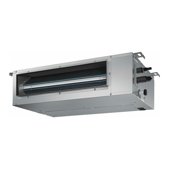
Summary and Features 1. Summary and Features Indoor unit Product Code Outdoor unit Product Code Power Supply Power Supply Intake SDVH12M-A3NA(I) KEF001N0310 SAVH12A-A3NA(O) KED001W0010 220-240V~, SDVH18M-A3NA(I) KEF001N0320 SAVH18A-A3NA(O) KED001W0020 Outdoor Unit 50Hz,1Ph SDVH24M-A3NA(I) KEF001N0350 SAVH24A-A3NA(O) KED001W0030 Indoor Unit Model: SDVH12M-A3NA(I) ,SDVH18M-A3NA(I),SDVH24M-A3NA(I) Wired Controller XKRB1... - Page 4 Summary and Features Outdoor Unit SAVH12A-A3NA(O) SAVH18A-A3NA(O) SAVH24A-A3NA(O)
-
Page 5: Safety Precautions
Safety Precautions 2. Safety Precautions Installing, starting up, and servicing air conditioner can be hazardous due to system pressure, electrical components, and equipment location, etc.Only trained, qualified installers and service personnel are allowed to install, start-up, and service this equipment.Untrained personnel can perform basic maintenance functions such as cleaning coils. All other operations should be performed by trained service personnel.When handling the equipment, observe precautions in the manual and on tags, stickers, and labels attached to the equipment. - Page 6 Safety Precautions Please read this operating manual carefully before operating the unit. Appliance filled with flammable gas R32. Before use the appliance, read the owner's manual first. Befoer install the appliance,read the installation manual first. Befoer repair the appliance ,read the service manual first. The figures in this manual may be different with the material objects ,please refer to the material objects for reference.
-
Page 7: Specifications
Specifications 3. Specifications 3.1 Unit Specifications Model SDVH12M-A3NA(I) SDVH18M-A3NA(I) SAVH12A-A3NA(O) SAVH18A-A3NA(O) Product Code KEF001N0310/KED001W0010 KEF001N0320/ KED001W0020 Rated Voltage 220-240 220-240 Power Rated Frequency Supply Phases Power Supply Mode outdoor outdoor Cross-sectional Area of Power Cable Conductor Recommended Power Cable(Core) Cross-sectional Area of Connecting Cable Conductor 0.75 0.75 Recommended Connecting Cable(Core) - Page 8 Specifications Evaporator Form Aluminum Fin-copper Tube Aluminum Fin-copper Tube Evaporator Pipe Diameter Φ7 Φ7 Evaporator Row-fin Gap Evaporator Coil Length (L×D×W) 805×38.1×228.6 805×38.1×228.6 Set Temperature Range 16~31 16~31 ℃ Sound Pressure Level dB (A) 42/41/30/27 45/42/39/36 Indoor Sound Power Level dB (A) 54/51/40/37 56/52/49/46...
- Page 9 Specifications Model SDVH24M-A3NA(I)/SAVH24A-A3NA(O) Product Code KEF001N0350/KED001W0030 Rated Voltage 220-240 Power Rated Frequency Supply Phases Power Supply Mode outdoor Cross-sectional Area of Power Cable Conductor Recommended Power Cable(Core) Cross-sectional Area of Connecting Cable Conductor 0.75 Recommended Connecting Cable(Core) Min/Max. Voltage 198/264 Cooling Capacity 7000 Cooling Capacity...
- Page 10 Specifications Swing Motor Power Output Fuse Current Set Temperature Range 16~31 ℃ Sound Pressure Level dB (A) 45/42/40/34 Sound Power Level dB (A) 56/52/50/44 Indoor Dimension (W×H×D) 1300×450×200 Unit Dimension of Carton Box (W×H×D) 1486×536×249 Dimension of Package(W×H×D) 1489×539×266 Stacked Layers Net Weight Gross Weight Outdoor Unit Model...
-
Page 11: Operation Characteristic Curve
Specifications 3.2 Operation Characteristic Curve Cooling Heating Condition Condition Indoor:DB 20°C Indoor:DB 27°C WB19°C Indoor air flow: Super High Indoor air flow: Super High Pipe length:5m Pipe length:5m Voltage:230V Voltage:230V Compressor Speed(rps) Compressor Speed(rps) 3.3 Capacity Variation Ratio According to Temperature Heating operation ambient temperature range is -20ºC~24ºC Cooling Heating... -
Page 12: Noise Curve
Specifications 3.4 Noise Curve ● 12K Indoor side noise when blowing Outdoor side noise when blowing 12K Heating 12K Cooling Super High Middle High Indoor fan motor rotating speed Compressor frequency(Hz) ● 18K&24K Indoor side noise when blowing Outdoor side noise when blowing 18&24K Heating 18&24K Cooling Super High... -
Page 13: Function And Control
Function and Control 4. Function and Control 4.1 Wired Controller Operations Liquid crystal display FRESH-AIR G-CONTROL Icon Name Icon Instruction NO. Icon Name Icon Instruction Wifi Wi-fi Is On 2 TEMP. Ambient Temp. / Setting Temp. Auto Operating In Auto Mode 3 Fan Speed Current Setting Fan Speed Cooling Operating In Cooling Mode... - Page 14 Function and Control Bottoms Button Name Button Instruction Switch Turn on/off unit Mode Select the operating mode : Auto, Cooling,Dry,Fan,Heating 1. Setting operating temp., range:16-31°C (61°F-88°F) 2. Setting timer time, range: 0.5-24 hour Adjust fan speed Function Select Clean, Eco, Sleep, Turbo, Quiet, etc. Fuctions. 1.
- Page 15 Function and Control On/Off Press the " " button to turn on or off the unit. Mode Setting In on-state, press the " " button to switch the operation modes as the sequence shown in below: FRESH-AIR G-CONTROL Auto Cooling Heating Note: You cannot set to a mode from the wired controller of the indoor unit that conflicts with the master...
- Page 16 Function and Control Clock Setting Whether the system is on or off, press and hold the " " button for 5 seconds to access the system clock menu. The " " icon will appear and the " " icon will flash while the timer area displays the current system clock. Press the " "...
- Page 17 Function and Control Countdown Timer ● Set Timer Press the " " button to enter the Timer OFF (ON) setting interface. The " " display and a flashing "HOUR" icon will appear. Press the " " or " " button to adjust the timer to your desire and then press the " "...
- Page 18 Function and Control Eco Setting The minimum and maximum temperature limits for Cooling/Dry (Heating) modes can be used so that the Air conditioner operates in a narrower temperature range and thus saves energy. ● Set the Eco function: In Cooling/Dry (Heating) mode, press the " "...
- Page 19 Function and Control DRY Setting Dry function: After the unit is turned off, the air conditioner runs automatically to blow-dry the water in the evaporator in the indoor unit to avoid the build-up of mildew. In cooling or dry mode, press the " "...
- Page 20 Function and Control Child lock Setting Press and hold the " " and " " buttons at the same time for 5 seconds to enter the child lockstate. " " is displayed on the LCD. Press the " " and " "...
- Page 21 Function and Control Parameter Range and Set Parameter Code Parameter Name Description Meaning 1.When set to 00, the current master and slave states are not 00: do not change settings Setting for a master indoor unit changed; 01: enabled When set to 01, the current indoor unit will be changed to the master.
-
Page 22: Description Of Each Control Operation
Function and Control 4.2 Description of Each Control Operation 4.2.1 The mainboard design with below function (1) Auto (2) Cooling (3) Dehumidifying (4) Air fan (5) Heating 4.2.2 Control Indoor fan(Quiet、speed 1、speed 2、speed 3、speed 4、speed 5、Turbo), left and right louver, up and down louver, buzzer, display, outdoor electric heater(option), outdoor power, healthy(option). - Page 23 Function and Control 4.2.6 Other Function (1) Auto button when you press this button,it will enter auto mode,indoor motor in auto fan speed,Indoor fan run and louver motor stop. Press the auto button,unit will be off. (2) Filter cleaning Indoor motor fan run 600 hours ,unit will show CL to notice filter cleaning.The CL is off after turn off unit (3) Health Indoor healthy function start when push healthy button.
-
Page 24: Installation Manual
Installation Manual 5. Installation Manual 5.1 Safety operation of flammable refrigerant 5.1.1 Qualification requirement for installation and maintenance man All the work men who are engaging in the refrigeration system should bear thevalid certification awarded by the authoritative organization and the qualificationfor dealing with the refrigeration system recognized by this industry. If it needsother technician to maintain and repair the appliance, they should be supervisedby the person who bears the qualification for using the flammable refrigerant.It can only be repaired by the method suggested by the equipment’s manufacturer. -
Page 25: Notices For Installation
Installation Manual 5.1.6 Installation prepare To ensure safety, please be mindful of the following precautions. WARNING 1. When installing or relocating the unit, be sure to keep the refrigerant circuit free from air or substances other than the specified refrigerant. —... - Page 26 Installation Manual 5.2.1 Installation Site Instructions Installing the unit in the following places maycause malfunction. If it is unavoidable, please consult the local dealer: 1.The place with strong heat sources,vapors,flammable or explosive gas,or volatile objects spread in the air. 2.The place with high-frequency devices (such as welding machine,medical equipment). 3.The place near coast area.
-
Page 27: Installation Of Wired Controller
Installation Manual 5.3 Installation of Wired Controller 5.3.1 Installation of Wired Controller The simple installation step of wired controller is as shown on the figure, please notice below issues: ● Pull out the 4 core twisted pair wire from the mounting hole and pass this line through the oblong hole located at the bottom of the wired controller. -
Page 28: Installation Indoor Unit
Installation Manual 5.4 Installation Indoor Unit Dimension Requirements on the Installation Space of the Indoor Unit Installation of the Indoor Unit a. Requirements on the Installation Location 1. Ensure the hanger is strong enough to withstand the weight of the unit. 2. - Page 29 Installation Manual 3. Horizontal Check of the Indoor Unit After the installation of the indoor unit, its horizontal must be checked to make sure the unit keep horizontal fore and aft and keep an inclination of 1° toward the drain pipe right and left. Horizontal tester CAUTION! ●...
- Page 30 Installation Manual CAUTION! Hold the torque wrench at its grip, keeping it in the right angle with the pipe in order to tighten the flare nut correctly. Torque wrench Holding spanner Oil applied (to reduce friction with the flare nut) Copper piping Spanner Torque wrench...
- Page 31 Installation Manual Enlarged View As the inside of the unit is in the negative pressure status, it is required to set Condensate Drain pipe up a backwater elbow. The requirements is: A=B ≥ P/10+20(mm) P is the absolute pressure inside the unit. The unit of the pressure is Pa.
- Page 32 Installation Manual b. Installation of the Air Supply Duct 1. Installation of the rectangular air supply duct Name Name Hanger Filter Air Intake Pipe Main Air Supply Pipe Canvas Air Pipe Air Supply Outlet Air Intake CAUTION! ● The maximum length of the duct means the maximum length of the supply air duct plus the maximum length of the return air duct. ●...
- Page 33 Installation Manual 2. Put the elastic buckle into the metal sheet at the air inlet downside of the unit. Electrical Wiring Elastic buckle a. Wiring Precautions WARNING! ● Before obtaining access to terminals, all supply circuits must be disconnected. ● The rated voltage of the unit is as shown as table 7. ●...
-
Page 34: Installation Outdoor Unit
Installation Manual CAUTION! ● Before starting work, check that power is not being supplied to the outdoor unit. ● Match the terminal block numbers and connection cord colors with those of the indoor unit side. ● Erroneous wiring may cause burning of the electric parts. ●... - Page 35 Installation Manual Install drain joint (Only for cooling and heating unit) 1. Connect the outdoor drain joint into the hole on the chassis, as shown in the picture below. 2. Connect the drain hose into the drain vent. drain joint Fix outdoor unit 1.
- Page 36 Installation Manual Neaten the pipes 1. The pipes should be placed along the wall,bent reasonably and hidden possibly. Min. semidiameter of bending the pipe is 10cm. 2. If the outdoor unit is higher than the wall hole, you must set a U-shaped curve in the pipe before pipe goes into the room, in order to prevent rain from getting into the room.
-
Page 37: Check After Installation
Installation Manual 5.6 Check after installation Check according to the following requirement after finishing installation. Items to be checked Possible malfunction Has the unit been installed firmly? The unit may drop, shake or emit noise It may cause in sufficient cooling(heating) Have you done the refrigerant leakage test? capacity. -
Page 38: Configuration Of Connection Pipe
Installation Manual 5.8 Configuration of connection pipe 1. Standard length of connection pipe ● 5m, 7.5m, 8m. 2. Min. length of connection pipe is 3m. 3. Max. length of connection pipe and max. high difference. Max length Max height Max length Max height Cooling capacity Cooling capacity... -
Page 39: Pipe Expanding Method
Installation Manual 5.9 Pipe expanding method Improper pipe expanding is the main cause of refrigerant leakage. Please expand the pipe according to the following steps: A: Cut the pipe Confirm the pipe length according to the distance of indoor unit and outdoor unit. Cut the required pipe with pipe cutter. pipe pipe cutter leaning... -
Page 40: Construction Views
Construction Views 6. Construction Views 6.1 Indoor Unit Fig.2 Outline Dimensions Item Model SDVH12M-A3NA(I) SDVH18M-A3NA(I) 1040 1000 SDVH24M-A3NA(I) 1340 1300 6.2 Outdoor Unit Model: SAVH12A-A3NA(O) Unit:mm... - Page 41 Construction Views Model: SAVH18A-A3NA(O) Model: SAVH24A-A3NA(O) Unit:mm...
-
Page 42: Exploded Views And Parts List
Exploded Views and Parts List 7. Exploded Views and Parts List 7.1 Indoor Unit Model:SDVH12M-A3NA(I) - Page 43 Exploded Views and Parts List Part Code Description SMVH09D-1B1A3NA(I) Product Code KEF001N0310 Left-side Plate Assembly K1060001601 Motor Support K11200014 Motor K1680001202 Under Volute K15800007 Centrifugal Fan Subassemble K14420005 Up Volute K15800006 Motor Clamp K6080000301 Motor Loop Clamp K60800004 Motor Clamp Subassembly K60800002 Filter Assembly K15420035...
- Page 44 Exploded Views and Parts List Model:SDVH18M-A3NA(I) 19 20 21 22 23 24...
- Page 45 Exploded Views and Parts List Part Code Description SDVH18M-A3NA(I) Product Code KEF001N0320 Wind-casing Assembly K11260017 Under Cover Plate 1 K20600016 Drain Pan Assembly K16410008 Evaporator Subassembly K10200059 Motor Installation Plate Subassembly K11230010 Bearing Pedestal(left) K22040004 Left-side Plate Assembly K1060001601 Bearing Installation Case K10610001 Bearing Gum Ring Subassembly K62400007...
- Page 46 Exploded Views and Parts List Model:SDVH24M-A3NA(I) 5 6 7 8...
- Page 47 Exploded Views and Parts List Part Code Description SDVH24M-A3NA(I) Product Code KEF001N0350 Air Filter Subassembly K15420035 Support K11280001 Under Cover Plate 2 K20600008 Motor K16800032 Motor Loop Clamp K60800004 Motor Clamp Subassembly K60800002 Motor Clamp K6080000301 Motor Support K11200014 Coupling K61200009 Rotate Axis Subassembly K61200010...
-
Page 48: Outdoor Unit
Exploded Views and Parts List 7.2 Outdoor Unit Model: SAVH12A-A3NA(O) - Page 49 Exploded Views and Parts List Part Code Description SAVH12A-A3NA(O) Product Code KED001W0010 Grill(apricot Grey) K21600001 Axial Flow Fan(Original Color) K15010001 Motor K16800008 Front Panel(apricot Grey) K11010001P Left Side Panel K10600067 Chassis Subassembly K10400115 Motor Support K11200028 Top Cover(Apricot Grey) K10450004P Reactor K34020001 Partition Board Subassembly...
- Page 50 Exploded Views and Parts List Model: SAVH18A-A3NA(O)
- Page 51 Exploded Views and Parts List Part Code Description SAVH18A-A3NA(O) Product Code KED001W0020 Grill(Apricot Grey) K21600005 Front Panel(Apricot Grey) K11010007P Axial Flow Fan(Original Color) K15010005 Odu Fan Motor K16800028 Left Side Panel(Apricot Grey) K10600031P Chassis Subassembly K10400110P Motor Support Subassembly K1120001703 Top Cover(Apricot Grey) K10450034P Condenser Assembly...
- Page 52 Exploded Views and Parts List Model: SAVH24A-A3NA(O) 33 32...
- Page 53 Exploded Views and Parts List Part Code Description SAVH24A-A3NA(O) Product Code KED001W0030 Grill(Apricot Grey) K21600002 Front Panel(Apricot Grey) K11010002P Axial Flow Fan(Original Color) K15010002 Odu Fan Motor K16800015 Chassis Rubber Plug K62600009 Left Side Panel(Apricot Grey) K10600005P Little Handle K22210004 Chassis Subassembly K11034039P Top Cover(apricot Grey...
-
Page 54: Schematic Diagram
Schematic Diagram 8. Schematic Diagram 8.1 Electrical Wiring Meaning of marks Symbol YEGN Color symbol ORANGE WHITE YELLOW YELLOW GREEN BROWN BLUE BLACK VIOLET Symbol COMP. 4WAY Name COMPRESSOR 4-WAY VALVE ELECTRONIC EXPANSION VALVE PROTECTIVE EARTH ◆ Indoor Unit These circuit diagrams are subject to change without notice, please refer to the one supplied with the unit. - Page 55 Schematic Diagram ◆ Outdoor Unit COMP Please don’t touch any electronic component or terminal when the machine is running,stopping or has been powered off for less than 30 minutes to prevent the risk of electric shock! These circuit diagrams are subject to change without notice, please refer to the one supplied with the unit.
-
Page 56: Pcb Printed Diagram
Schematic Diagram 8.2 PCB Printed Diagram 8.2.1 Indoor Unit Function access interface water full detection wire controller communication interface temperature sensor display board interface DC water pump interface communication interface between indoor unit and outdoor unit 220V AC fire line 220V AC neutral line... - Page 57 Schematic Diagram 8.2.2 Outdoor Unit Model: SAVH12A-A3NA(O) Top View NO. Silk scren name Connector Function note U(BU), Compressor interface Used to connect the compressor: U (BU) - (YE) - yellow blue, V, W (RD) - red V(YE),W(RD) Overload interface Used to connect the compressor overload protector, the two white lines. Random selection Used to connect to the six core thermal package: tube temperature (20 k @ 25 TEMP Temp.sensor interface...
- Page 58 Schematic Diagram Bottom View Name Compressor control circuit Compressor phase current sampling circuit & PFC current sampling circuit Power factor correction (PFC) control circuit Master control chip circuit DC fan electric circuit, sampling circuit Switch power supply circuit Wire communication circuit Fan and load control circuit...
- Page 59 Troubleshooting Model: SAVH18A-A3NA(O) ● Top view NO. Silk scren name Connector Function note U(BU), Compressor interface Used to connect the compressor: U (BU) - (YE) - yellow blue, V, W (RD) - red V(YE),W(RD) Overload interface Used to connect the compressor overload protector, the two white lines. Random selection Used to connect to the six core thermal package: tube temperature (20 k @ 25 TEMP Temp.sensor interface...
- Page 60 Troubleshooting ● Bottom view Name Compressor control circuit Compressor phase current sampling circuit & PFC current sampling circuit Power factor correction (PFC) control circuit Master control chip circuit DC fan electric circuit, sampling circuit Switch power supply circuit Wire communication circuit Fan and load control circuit...
- Page 61 Troubleshooting Model: SAVH24A-A3NA(O) ● Top view NO. Silk scren name Connector Function note U(BU), Compressor interface Used to connect the compressor: U (BU) - (YE) - yellow blue, V, W (RD) - red V(YE),W(RD) Overload interface Used to connect the compressor overload protector, the two white lines. Random selection Electronic expansion valve interface Used to connect five core electronic expansion valve Used to connect to the six core thermal package: tube temperature (20 k @ 25 ℃...
- Page 62 Troubleshooting ● Bottom view Name Compressor control circuit Compressor phase current sampling circuit & PFC current sampling circuit Power factor correction (PFC) control circuit Master control chip circuit DC fan electric circuit, sampling circuit Switch power supply circuit EMI filter circuit Wire communication circuit Fan and load control circuit...
-
Page 63: Troubleshooting
Troubleshooting 9. Troubleshooting 9.1 Error Code List Way of display By remote control By remote Error Name of malfunction and procedure within Error Possible Causes Solution Display conrol compressor stop Type Code status directly procedure 200s or direcly only after compressor stop 200s Filter cleaning reminder √... - Page 64 Troubleshooting Compressor phase √ Outdoor See Diagram 6 See Diagram 6 current peak protection Compressor phase √ Outdoor See Diagram 7 See Diagram 7 current RMS protection IPM protection √ Outdoor See Diagram 8 See Diagram 8 1. Check the radiator 1.
- Page 65 Troubleshooting 1. Check the outdoor unit 1. The outdoor unit valve is valve is open. close. 2. The refrigerant connecting 2. The refrigerant connecting pipe installation errors. pipe installation errors. 3. Check the inside and Indoor and outdoor 3. The inside and outside √...
-
Page 66: Procedure Of Troubleshooting
Troubleshooting 9.2 Procedure of Troubleshooting Diagram 1: E0 Start System Abnormal System Problem problem (Such: Stop etc) solved Solutions Outdoor motor abnormal speed Resolve rotate Problem speed problem (Under Cooling mode) solved Outdoor Resolve air abnormal intake Problem inlet problem (Under Cooling mode) solved The system is normal,... - Page 67 Troubleshooting Diagram 2: Main test points: ● Is the temperature of Indoor and Outdoor Unit too high? ● Is the fan of Indoor and Outdoor Unit operating normal? ● Is the radiating of Indoor and Outdoor Unit well(Including the fan speed is lower or not )? ●...
- Page 68 Troubleshooting Diagram 3: Main test points: ● Check the electronic expansion valve is connected. ● Check the electronic expansion valve is in good condition. ● Check the refrigerant leakage or not. ● Check the overload protector is in good condition. ●...
- Page 69 Troubleshooting Diagram 4: Main test points: ● Check the system pressure is high. ● Check the voltage is low. Step out during the Step out problem happen operation after power on Check the Check the fan terminals Change fan motor Check the outside fan compressor stop capacity C1...
- Page 70 Troubleshooting Diagram 5: Main test points: ● Whether the compressor wiring is connected correct? ● Is compressor broken? ● Is time for compressor stopping enough? ● Whether refrigerant was charged too much? Power on the unit Is stop time of the Restart it up after 3 minutes compressor longer than 3 minutes?
- Page 71 Troubleshooting Diagram 6 , 7, 8: Main check points: ●Is the connection between control panel AP1 and compressor COMP secure? Loose? Is the connection in correct order? ●Is the voltage input of the machine within normal range? (Use AC voltmeter to measure the voltage between terminal L and N on the wiring board XT) ●Is the compressor coil resistance normal? Is the insulation of compressor coil against the copper tube in good condition? ●Is the working load of the machine too high? Is the radiation good? ●Is the charge volume of refrigerant correct?
- Page 72 Troubleshooting Diagram 9: Main detection points: Is there jumper cap on the main board? Is the jumper cap inserted correctly and tightly? The jumper is broken? The motor is broken? Malfunction diagnosis process: Start Is there jumper cap on the mainboard? Assemble the jumper cap with the same model Is malfunction...
- Page 73 Troubleshooting Diagram 10: Malfunction of Blocked Protection of IDU Fan Motor L2 Main detection points: SmoothlyIs the control terminal of PG motor connected tightly? SmoothlyIs the feedback interface of PG motor connected tightly? The fan motor can't operate? The motor is broken? Malfunction diagnosis process: Start While power is off stir the blade...
- Page 74 Troubleshooting Diagram 11: Main check points: ● Test the indoor and outdoor unit connection wire and internal wiring is connected or in good condition. ● Check the indoor unit main board communication circuit and outdoor unit main board communication circuit (AP1)are in good condition. Start The unit operating normal before the fault been found...
- Page 75 Troubleshooting Diagram 12: Outdoor unit communication circuit detection process as follows ( outdoor unit key test points) Start Use the Tesr 10 position to test voltage values by voltmeter Numerical change Use the Tesr 13 position to test voltage values by voltmeter Numerical change Outdoor unit error...
- Page 76 Troubleshooting Diagram 13: P7 Troubleshooting Start The power supply voltage The normal nameplate voltage Error declared is not stable with volatility. rated wiithin 10% range The power supply voltage Adjust the power supply voltage, ensure Error declared is low and overload. that the voltage keep in normal range Make sure indoor and Clean the...
- Page 77 Troubleshooting Diagram 14: Power factor correct (PFC) fault P9 (a fault of outdoor unit) (AP1 here in after refers to the control board of the outdoor unit) Mainly detect: ● Check if the reactor (L) of the outdoor unit and the PFC capacitor are broken. Fault diagnosis process: Start Check wiring of the...
- Page 78 Troubleshooting 9.3 Troubleshooting for Normal Malfunction 1. Air Conditioner Can't be Started Up Possible Causes Discriminating Method (Air conditioner Status) Troubleshooting Confirm whether it's due to power failure. If No power supply, or poor After energization, operation indicator isn’t bright yes,wait for power recovery.
- Page 79 Troubleshooting 4. ODU Fan Motor Can't Operate Possible Causes Discriminating Method (Air conditioner Status) Troubleshooting Connect wires according to wiring diagram to Wrong wire connection, or poor Check the wiring status according to circuit make sure all wiring terminals are connected connection diagram firml...
- Page 80 Troubleshooting Appendix1:Resistance Table for Indoor and Outdoor Ambient Temperature Sensors (15K) Temp.(℃ ) Resistance(kΩ) Temp.(℃ ) Resistance(kΩ) Temp.(℃ ) Resistance(kΩ) Temp.(℃ ) Resistance(kΩ) 22.53 4.986 1.451 138.1 21.51 4.802 1.408 128.6 20.54 4.625 1.363 121.6 19.63 4.456 1.322 18.75 4.294 1.282 108.7 17.93...
- Page 81 Troubleshooting Appendix2:ResistanceTable for Indoor and Outdoor Ambient Temperature Sensors (20K) Temp.(℃ ) Resistance(kΩ) Temp.(℃ ) Resistance(kΩ) Temp.(℃ ) Resistance(kΩ) Temp.(℃ ) Resistance(kΩ) 361.8 48.42 9.803 2.663 339.8 46.11 9.42 2.577 319.2 43.92 9.054 2.495 41.84 8.705 2.415 282.2 39.87 8.37 2.339 265.5 38.01...
- Page 82 Troubleshooting Appendix 3: Resistance Table for Indoor and Outdoor Ambient Temperature Sensors (50K) Temp. Resistance Temp. Resistance Temp. Resistance Temp. Resistance (k ) (k ) (k ) (k ) 894.497 121.073 24.544 6.565 23.584 841.108 6.350 115.255 22.667 6.143 791.159 109.752 744.415 21.790...
-
Page 83: Removal Procedure
Removal Procedure 10. Removal Procedure 10.1 Removal Procedure of Indoor Unit Warning Be sure to wait for a minimum of 10 minutes after turning off all power supplies before disassembly. Procedure Note 1. Before disassembly 2. Remove electric box cover Remove the screws on electric box by screws-drivers and then lift-up, Loose buckles of electric box bottom and then remove... - Page 84 Removal Procedure Procedure Note 4. Remove air outlet assembly Loose the screws on air outlet assembly by screws-drivers and then remove air outlet assembly. 5. Remove lower cover plate1 Loose the screws on lower cover plate1 by screws-drivers and then remove lower cover plate1.
- Page 85 Removal Procedure Procedure Note 7. Remove electric box assembly Remove the screws on electric box assembly by screws- drivers,loose the cables with all components ,lift-up and then remove electric box assembly. 8. Remove right plate. right plate A: Loose the screws on seaplate for feed nozzle seaplate for feed nozzle by screws-drivers and remove seaplate for feed nozzle.
- Page 86 Removal Procedure Procedure Note 10.Remove evaporator A: Lift-up evaporator and remove evaporator. Note: Please check step 6 to remove evaporator, and loose the fixed screws among evaporator,left plate,right plate and sealplate, lift-up evaporator and take out liquid pipe and windpipe from right plate and then remove the evaporator assembly.
-
Page 87: Removal Procedure Of Outdoor Unit
Removal Procedure 10.2 Removal Procedure of Outdoor Unit Warning Be sure to wait for a minimum of 10 minutes after turning off all power supplies before disassembly. Procedure Note 1.Before disassembly Screw 2. Remove top cover Top cover Remove connection screws connecting the top cover plate with the front panel and the right side plate, and then remove the top panel. - Page 88 Removal Procedure Procedure Note 4.Remove grille and panel A: Remove connection screws between the front grille and the front panel. Then remove the front grille. B: Remove connection screws connecting the front panel with the chassis and the motor support, and then remove the front panel. Grille Front panel Screw...
- Page 89 Removal Procedure Procedure Note 7. Remove left side plate Remove connection screws connecting the left side plate with the condenser assy. Then remove the left side plate. Left side plate 8. Remove right side plate Right side plate Remove connection screws connecting the right side plate with the valve support and the electric box.
- Page 90 Removal Procedure Procedure Note 10. Remove Reactor Take off the fixed screw,and you could take off the reactor. Reactor Screw 11. Remove motor and motor support Motor support Remove tapping screws fixing the motor and disconnect the leading wire insert of the motor. Motor Then remove the motor.
- Page 91 Removal Procedure Procedure Note 13. Remove 4-way valve assy Unsolder the spot weld of 4-way valve assy, compressor and condenser, and then remove the 4-way valve assy. Warning 4-way valve assy Discharge the refrigerant completely before unsoldering,when unsoldering, wrap the gas valve with awet cloth completely to avoid damage to the valve caused by high temperature.
- Page 92 Removal Procedure Procedure Note 15. Remove Expansion valve Assy Unsolder the spot weld of expansion valve Expansion valve Assy assy, liquid valve and condenser, and then remove the expansion valve assy . 16. Remove the compressor A: Remove the 2 screws fixing the gas valve and unsolder the welding joint between the gas valve and the air-return pipe to remove the gas valve.
- Page 93 SHENZHEN SKYWORTH AIR CONDITIONING TECHNOLOGY CO. LTD NO.12 GAOKE AVENUE BAOLONG INDUSTRIAL CITY LONGGANG DISTRICT SHENZHEN GUANGDONG CHINA. Web: www.skyworth-ac.com Tel: (+86-755)26743958...
Need help?
Do you have a question about the SDVH12M-A3NAI and is the answer not in the manual?
Questions and answers