Table of Contents
Advertisement
Quick Links
Stabilimento / Plant
Via Bicocca 14/c - 40026 Imola (Bo) Italy
Tel. (+39) 0542 653441 - Fax (+39) 0542 653555
www.ce adentale.it - ce adentale@ce a.it
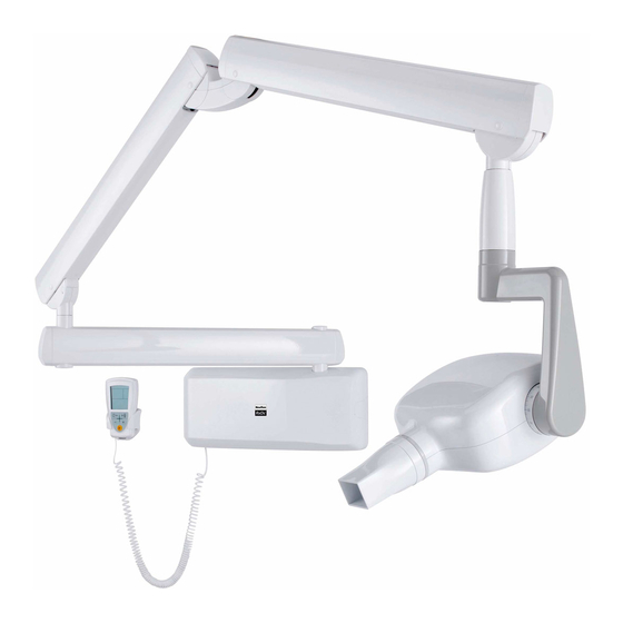
X-ray unit
RX DC
T e c h n i c a l m a n u a l
C o d . 9 7 0 7 1 1 0 7 r e v . 5
A f t e r S a l e s S e r v i c e - P l a n t V i a B i c o c c a 1 4 / c 4 0 0 2 6 I m o l a ( B O )
I t a l y - Te l . + 3 9 0 5 4 2 6 5 3 7 4 2 - F a x + 3 9 0 5 4 2 653596
Advertisement
Table of Contents

Related Manuals for CEFLA RX DC


Summary of Contents for CEFLA RX DC
- Page 1 X-ray unit RX DC T e c h n i c a l m a n u a l C o d . 9 7 0 7 1 1 0 7 r e v . 5 Stabilimento / Plant Via Bicocca 14/c - 40026 Imola (Bo) Italy A f t e r S a l e s S e r v i c e - P l a n t V i a B i c o c c a 1 4 / c 4 0 0 2 6 I m o l a ( B O ) Tel.
-
Page 2: Table Of Contents
4.3.1. PASS THROUGH installation extension arm ..................8 4.4. Installing the double pantograph arm ......................9 4.5. Installing the RX DC with "ball end socket joint" generator ................11 4.6. Installing the RX DC with standard joint generator ..................11 4.7. Installing the collimator ..........................14 4.8. - Page 3 19.2. Check occupation of radiofrequencies for RXDC PDA ................42 19.3 How to disable the channels that are excessively noisy................43 20. RX DC with "ball end socket joint" / With standard joint - INSTALLATION CHECK LIST FOR USA ONLY ..47 with "ball end socket joint"...
-
Page 4: General Safety Precautions
RX DC X-RAY UNIT 1. General safety precautions Cefla Sc - Cefla Dental Group guarantees the safety, reliability and performance of the equipment under the following conditions: - Installation and technical service is performed by authorized technicians using Cefla Sc - Cefla Dental Group original spare parts. -
Page 5: Before Installation
RX DC X-RAY UNIT 3. Before installation 3.1. Mechanical specifications required If the wall is thin (hollow bricks or similar), use the backplate (part no. 9660048) to be mounted on the wall or placed on the side of the wall opposite the wall where the unit is to be installed. -
Page 6: Installation
RX DC X-RAY UNIT 4. Installation The x-ray unit must be installed by a qualified technician in compliance with the installation instructions given below as regards both the mechanical and electrical parts. WARNING! Always check that the voltage indicated on the generator’s nameplate corresponds to that for the electrical system. 4.1. Positioning the x-ray unit’s structure Figure POSITIONING Figure POSITIONING • Block the middle clamp in the opening provided (d) according... -
Page 7: Vertical Single Stud Installation With Wooden Post
RX DC X-RAY UNIT 4.2.1. Vertical SINGLE STUD installation with wooden post • Insert the 4 TPSEI M8x35 screws with heads that allow them to be driven with a screw driver provided in the interface plate • Run the power cord through one of the holes in the interface plate •... -
Page 8: Extension Arm
RX DC X-RAY UNIT 4.3. Extension arm WARNING! Do not lubricate the pin of the extension arm: the wall-mounted plate is provided with self-lubricating bushings. Figure B • Insert the pin (b) of the extension arm (c) in the hole provided in the wall-mounted plate. • Take the clutch (a) from the kit, install it on the plate using the corresponding screws and adjust the arm (c) as requi- red. -
Page 9: Pass Through Installation Extension Arm
RX DC X-RAY UNIT 4.3.1. PASS THROUGH installation extension arm Install inside cabinet model PXTG92 42.5'' x 49'' Switch at top h=191cm Check the direction of the pin support: it should be set as shown in figure (A) for this type of installation. Insert the extension arm pin in the hole in the wall-mounting plate from below. Place the washer supplied on top of the pin and forcefully tighten the ring nut with the pin spanner provided, as shown in the figure (B). -
Page 10: Installing The Double Pantograph Arm
RX DC X-RAY UNIT 4.4. Installing the double pantograph arm WARNING! The arms are supplied secured together by a belt. This belt should not be removed until the two free ends of the arms have been connected to their corresponding attachments: the extension arm (already secured to the wall) and x-ray head. If the belt is loosened before fixing the arms in place, releasing them abruptly could damage them and the operator risks being injured. Figure E • Take the washer (f) from the kit and position it at point (i) corresponding to the extension arm (c). • Pass the cable (m) of the pantograph arm (e) through the extension arm (c) so that it comes out of the hole below. - Page 11 RX DC X-RAY UNIT Figure F • Take the grubscrew used to stop rotation (o) from the x-ray unit kit and tighten it at point H (tighten it fully and then loosen by ½ turn). NOTE:Turn the pantograph arm to check that the adjustment has been made properly. • Take the clutch assembly (friction element, screw and 4 curved washers) from the x-ray unit kit and install it at point NOTE: Insert the curved washers (j) and the friction element (k) as indicated in figure F.
-
Page 12: Installing The Rx Dc With "Ball End Socket Joint" Generator
RX DC X-RAY UNIT 4.5. Installing the RX DC with "ball end socket joint" generator Figure I • Take the generator out of the packaging. • Insert the pin (a) in the sleeve making sure the respective openings match and secure with the screws (b) provided. • Insert the power cable in the generator’s pin and run it out of the opening (c) provided. - Page 13 RX DC X-RAY UNIT - Take the washer (a) from the kit supplied and fit it in the pin (b) with the protruding tooth (c) pointed towards the right- hand head. (see fig.K) Figure K Position the protruding tooth (c) of the washer (a) in zone 1 of the pin (b). (see fig. L) WARNING! DO NOT position the protruding tooth (c) of the washer (a) in zone 2 of the pin (b). Figure L - Insert the power supply cable of the pantograph arm in the generator pin until it comes out of the hole below (see point c –...
- Page 14 RX DC X-RAY UNIT Figure M - Fit the connector of the pantograph arm cable to that of the generator cable. - Place them inside the hole provided (c). - Fit the plug (e) supplied into the hole then tighten the screw that is already in place. (see fig. N)
-
Page 15: Installing The Collimator
RX DC with standard joint Figure O round or rectangular in the case of RX DC with "ball end socket joint" Figure P - Insert it in the generator and block it in place by turning clockwise. -
Page 16: Balancing The Double Pantograph Arm
RX DC X-RAY UNIT 4.8. Balancing the double pantograph arm Figure Q If the double pantograph arm does not stay in a stable position, adjust the spring tension by using an 8mm Allen wrench about 20cm long. • To adjust the arm (a) connected to the extension: position it as shown in the figure and place the wrench at point A. -
Page 17: Wall-Mounted Plate Wiring Connections
RX DC X-RAY UNIT 4.10. Wall-mounted plate wiring connections Figure S • Connect the power cable (LINE) to terminal K2, observing the following positions: - SUPPLY (BROWN WIRE) - GROUND (YELLOW/GREEN wire) N - NEUTRAL (BLUE wire) • Connect the generator’s power cable to the respective connectors, observing the following positions: K6 - brown wire and blue wire. -
Page 18: Completion Of Wall-Mounting Plate And Holder For Hand-Held
RX DC X-RAY UNIT 4.11. Completion of wall-mounting plate and holder for hand-held. Figure T and Figure U • Pick up the cover (a) and place it over the wall-mounting plate fully tightening the grub screws (b) provided and pre- screwed on the plate. • Place the cover (c) in the area shown in the figure. The door (d) will automatically close when the controller is clo- sed. -
Page 19: Factory Settings
RX DC X-RAY UNIT 5. Factory settings The x-ray unit is supplied with the following factory settings: • Anode current: 6/7 mA (NORM mode). • Sensitivty: level 19. • Handheld stand by: 5 minutes • Patient’s built: adult (ADULT symbol selected). •... -
Page 20: Turning On The Handheld
RX DC X-RAY UNIT 6.1.2. Turning on the handheld The handheld is turned on by pressing any key, except for the one for x-ray emission. A buzzer rings to confirm the apparatus has been turned on. The unit will be in the standard configuration described in detail in paragraph 5 and then search for the base it works with. -
Page 21: Automatic Handheld Shut Off
RX DC X-RAY UNIT The main functions of the keys on the handheld vary according to how they are pressed: BRIEFLY PRESSED (less than 3 sec.) PRESSED LONGER (more than 3 sec.) Changes over from ADULT to CHILD Saves, if permitted, the sensitivity of the new tme and vice versa (takes place when key selected. -
Page 22: Checking The Set Parameters
RX DC X-RAY UNIT 6.1.6. Checking the set parameters WARNING! Before actually taking an exposure, make sure the exposure parameters for the examination in progress are correctly set. Checking the collimator used. The icon on the handheld’s screen should be on or off, depending on the operating mode selected: - Icon ON: indicates that the cylindrical collimator (8") is activated. -
Page 23: Factory Settings
Battery charge level low or almost dead (causing the handheld to automatically shut off). NOTE: The batteries should be removed from the handheld if it is not going to be used for an extended period. 8. X-ray generator indicator light In RX DC with "ball end socket joint" versions, the x-ray generator comes with an indicator light (B) that signals apparatus status: • Purple color > x-ray unit on (regular condition) •... -
Page 24: Position Of The Patient
10. Putting the x-ray unit cone into the required position Position the x-ray head so that the cone is aligned with the image receiver. RX DC versions feature "ball end socket joint" technology that allows the x-ray head to turn endlessly on both the horizontal and vertical planes. The x-ray head is initially blocked by an electromechanical brake. -
Page 25: Position Of The X-Ray Plate Or Sensor
RX DC X-RAY UNIT 11. Position of the X-ray plate or sensor The parallel technique, where applicable, provides more accurate images in terms of size compared to the bisecting te- chnique. A rectangular collimator, with 30 cm focus-skin distance, is always preferable to obtain better quality pictures. -
Page 26: Checking The Exposure Time On The Display
RX DC X-RAY UNIT 12. Checking the exposure time on the display Before starting exposure, check the time setting on the handheld’s screen (see the tables with the original exposure times, paragraph 3.1.4). To change the value, use keys “+” and “-”. NOTE: Changing the exposure time is only temporary: if the new time is not stored in the memory it will be lost. -
Page 27: Setting The Mode And Exposure Time In User Mode
RX DC X-RAY UNIT Press keys at the same time , the actual sensitivity factor will be displayed. Use keys to change the value from 3 to 25. If the displayed value differs from the one previously saved, icon comes on. To quit this mode, press key . -
Page 28: Procedure To Be Followed When Taking The X-Ray
RX DC X-RAY UNIT 13 Procedure to be followed when taking the x-ray • Pick up the handheld and go a safe distance away (at least 2 meters) maintaining visual contact with the patient and x-ray unit during the exposure. Make sure “READY” is indicated. • Tell the patient to stay still. -
Page 29: Technician And User Setup Menu
P 04: Handheld code display P 05: Activates/deactivates the safety unlock mode (see section 14.1) (only RX DC with "ball end socket joint"). P 06: Selects the operating mode (En60, En63, En65 and AUTO). P 07: Sets the type of removable cone used Technician setup menu Hold down these two keys when in position P07 on the user menu, to go to the advanced setup menu (from P 10 to P 18). -
Page 30: Setting The Safety Unlock Mode
Activating/deactivating the USER mode Icon comes on to signal USER mode is activated. 14.1. Setting the safety unlock mode The RX DC x-ray unit has a safety unlock for the ball joint. The default setting allows the ball joint to be disengaged by simply touching one of the keys present on the front of the head. -
Page 31: Calibrating The X-Ray Head
RX DC X-RAY UNIT simultaneously. "rESS" will briefly appear and the handheld will be rebooted. 14.5. Calibrating the X-ray head This operation requires the execution of 20 shots, at a pre-set time of 0.01 s, during which X-ray emission occurs. It is therefore necessary to pay close attention. Turn on your handheld and menu position P17. To access this menu press the keys ,scroll the... -
Page 32: Actuator Unit (Only Rx Dc With "Ball End Socket Joint")
RX DC X-RAY UNIT 15. Actuator unit (only RX DC with "ball end socket joint") Adjusting and replacing the actuator Pull out the collimator and panel stop ring, take off the screw cover caps and loosen the screws that secure the lower cover. Work on grub screw A with an Allen wrench to adjust the pressure the brake applies on the ball. -
Page 33: Control Unit Card Code 97660515
RX DC X-RAY UNIT 16. Control unit card Code 97660515 1 2 3 4 5 6 1 2 3 SCHEDA CENTRALINA RX DC 97660515 DL1=V_LINE DL2=V_BUS DL3=BUS OK DL4=V_DRVR Open - 230V Close - 115V DL5=READY DL6=ENABLE DL7=V_CTRL DL8=HV_ON Diagnostic Led indicators Color Status Indicates 230Volt input voltage if 110Volt the led indicator is illuminated but not as V_LINE bright. -
Page 34: Basic Head Control Card Code 97660514
RX DC X-RAY UNIT 17. Basic head control card Code 97660514 1 2 3 4 5 6 FL_OUT GND_FIL V+15 CAP_SDA SCHEDA TESTATA RX DC CAP_CLK CONE_SW 97660514 HAND_SW1 HAND_SW2 DL1=DSP DL2=VDD DL3=CPU DL4=ERR DL5=NTWK DL6=CONE DL7=HNDL DL8=PWM DL9=ACT DL10=FIL V+15 EN_ACT EN_S/U HV_FB CPU led unit... - Page 35 RX DC X-RAY UNIT Diagnostic Led indicators DSP LED INDICATOR Color Status Yellow Flashing If the diagnostic Led indicator flashes: once a second everything is OK once every 0.5 a second count the times it flashes and check the error in the...
- Page 36 RX DC X-RAY UNIT In the event of a CPU fault, the status of the CPU leds is as follows: • DL3=CPU flashing yellow • DL4=ERR illuminated red Both conditions may be present at the same time. This indicates that two errors have been identified (from both the DSP and CPU) or the DSP caused a fault which, in turn, caused the CPU error.
- Page 37 RX DC X-RAY UNIT Detach all the connectors and work on the two support pins to pull out the card. Put the new card back in the correct position, being careful to run the cables behind the card support pins as shown in the figure. Make sure they do not pass in front of the x-ray collimator.
-
Page 38: Actuator Control Card Code 97660591
RX DC X-RAY UNIT 18. Actuator control card Code 97660591 V+15 CTRL EN_ACT SCHEDA STEPUP EN_S/U HV_FB 97660591 Diagnostic Led indicators Color Status Green Indicates 15Volt input voltage. Green Indicates 40Volt present to actuate the actuator Yellow Lights up when one of the two actuator control buttons is pressed. -
Page 39: X-Ray Head
RX DC X-RAY UNIT 19. X-ray head Replacement Follow the instructions given above to remove the basic head control card Code 97660514. Detach all the cables con- nected to the head that may get in the way. Loosen the screw A that secures the head, move it to the rear and lift it as shown in the figure. - Page 40 RX DC X-RAY UNIT Radiogenic palmtop computer-head association If the control palmtop computer or the head control Code 97660514 needs to be replaced it is only necessary to asso- ciate the palmtop with the head. To do this, you first need to set the head in combination mode (an operation that can be done in two different ways) then send a recognition signal from the head's remote control.
-
Page 41: Replacing The Slip Ring Assembly (Only Rx Dc With "Ball End Socket Joint")
RX DC X-RAY UNIT 19.1. Replacing the SLIP RING assembly (only RX DC with "ball end socket joint") 1) Pull off the collimator and ring that secures the panels, remove the caps that protect the screws and loosen the screws that secure the bottom cover. 2) Disconnect all the connectors and work on the two pins to remove card 97660514 3) Detach all the cables connected to the head that may get in the way. - Page 42 RX DC X-RAY UNIT 9) Secure the cables to the actuator unit with another clamp, as illustrated in the figure: 10) Connect the wires in the nine-pole connector provided, observing the colors as shown in the figure: Purple Grey Green...
-
Page 43: Check Occupation Of Radiofrequencies For Rxdc Pda
RX DC X-RAY UNIT 19.2. Check occupation of radiofrequencies for RXDC PDA The procedure described below enables the user to check the availability of radio frequencies on the channels of com- munication used by the RXDC remote control PDA. Open the battery compartment of the PDA and remove the batteries. -
Page 44: How To Disable The Channels That Are Excessively Noisy
RX DC X-RAY UNIT fig.3 If, on most channels, the values are higher than 80%, PDA features are guaranteed. During normal use, the PDA per- forms automatic scans of the channels available and uses the frequencies available for communication. Once the test on the radiofrequencies has been completed, remove the batteries again, moving selector 2 of the dip- switch shown in fig. - Page 45 RX DC X-RAY UNIT Error codes given on the handheld When an error appears on the handheld screen it can be reset by pressing keys to set the x-ray unit back to READY. If the error is still displayed even after pressing the two keys mentioned above, refer to the error code and solution given in the table below.
- Page 46 RX DC X-RAY UNIT E 15 DSP error DSP error detected. Check the error subcode by press keys E 16 “tooth” and “+” at the same time. 0001 Overvoltage HW. 0002 Overcurrent HW. 0004 Overvoltage SW. It may be caused by incorrect calibra- tion or after an extended period of inactivity, Perform the calibration procedure from menu P17.(par.14.5.) 0008 Overcurrent SW. It may be caused by incorrect calibra- tion or after an extended period of inactivity, Perform the calibration procedure from menu P17.(par.14.5)
- Page 47 RX DC X-RAY UNIT E 33 Head power cable disconnected or pinched 8030 Make sure the power cable for the x-ray unit is con- nected to the control unit card code 97660515. Mea- suring with tester the resistance between connector thick cables of power (typically brown and white or grey and purple).
-
Page 48: For Usa Only
INSTALLATION CHECKLIST (document a copy, along with the original manufacturer’s INSTALLATION AND TEST REPORT (document number 97011016) to CEFLA North America, Inc. 6125 Harris Technology Blvd. Charlotte, NC 28269 USA. number 97050716, supplied with the device It is the responsibility of the Assemblers (defined as “any person engaged in the business of assembling, replacing, or installing one or more components into a diagnostic x-ray system or subsystem”) to fill out and distribute the “Report of assembly”, using the Form FDA 2579, upon completion of an installation and within... - Page 49 DISEGNO RISERVATO A NORMA DI LEGGE VIETATA LA RIPRODUZIONE E LA DIVULGAZIONE...
Need help?
Do you have a question about the RX DC and is the answer not in the manual?
Questions and answers