Table of Contents
Advertisement
Quick Links
Click here to get to our homepage:
http://www.ge.com/indsys/pm/
S R 469 S TAT U S
S R 469 IN S E RV ICE
S E T P O IN T A C C E S S
C O M P U T E R RS 23 2
C O M P U T E R RS 48 5
A U X ILIA R Y R S 4 85
LO C K O U T
RE S E T
P O S S IB LE
R ES ET
M E S S A G E
N EX T
P RO G R A M P O RT
CANADA
215 Anderson Avenue, Markham, Ontario, L6E 1B3
Tel: (905) 294-6222 Fax: (905) 294-8512
Internet: http://www.ge.com/edc/pm/
M O TO R S TAT U S
OUTPUT RELAYS
S T O P P E D
R 1 T RIP
S TA RT IN G
R 2 A U X IL IA RY
R UN N IN G
R 3 A U X IL IA RY
O V E R LO A D P IC K UP
R 4 A LA R M
U NB A L A N C E P ICK U P
R 5 B LO C K S TA RT
R 6 S E R V IC E
G R O U N D P IC K U P
H O T RT D
LO S S O F LO A D
7
8
9
SETPOINT
MESSAGE
4
5
6
ACTUAL
1
2
3
ESCAPE
VAL UE
.
0
HE LP
ENTER
TM
M O TO R M A NA G E M E N T
R E LAY
;39:99$71&'5
SR469
MOTOR MANAGEMENT RELAY
Instruction Manual
SR469 Revision: 30D260A8.000
SR469 PC Software Revision: 2.6
Manual P/N: 1601-0057-D7
Copyright 1998 GE Multilin
®
Advertisement
Table of Contents

Related Manuals for Multilin SR469


Summary of Contents for Multilin SR469
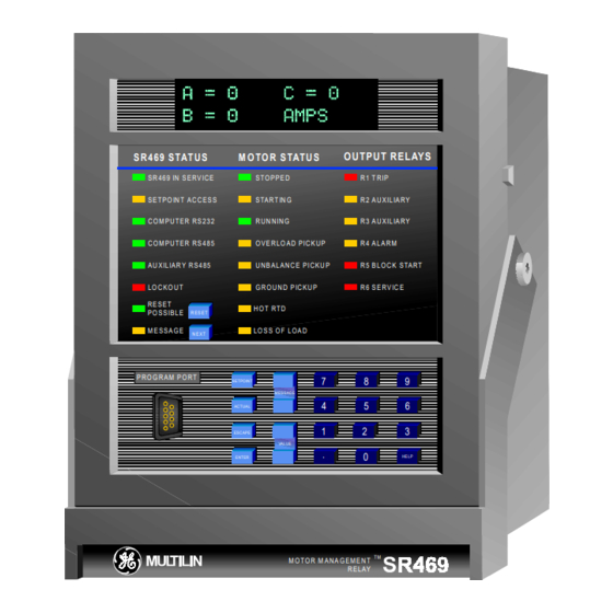
- Page 1 SR469 ® MOTOR MANAGEMENT RELAY Instruction Manual SR469 Revision: 30D260A8.000 SR469 PC Software Revision: 2.6 Manual P/N: 1601-0057-D7 Copyright 1998 GE Multilin S R 469 S TAT U S M O TO R S TAT U S OUTPUT RELAYS...
-
Page 2: Table Of Contents
SR469 MANUAL TABLE OF CONTENTS 1. INTRODUCTION........................1-1 1.1 OVERVIEW ..................................1-1 1.2 ORDER INFORMATION ............................... 1-3 1.3 SR469 SPECIFICATIONS ..............................1-4 2. INSTALLATION ........................2-1 2.1 MECHANICAL ..................................2-1 2.1.1 DESCRIPTION .......................................2-1 2.1.2 PRODUCT IDENTIFICATION ..................................2-2 2.1.3 INSTALLATION ......................................2-3 2.1.4 UNIT WITHDRAWAL AND INSERTION ................................2-4 2.1.5 TERMINAL LOCATIONS....................................2-5... - Page 3 4.5 S4 OUTPUT RELAYS................................. 4-21 4.5.1 RELAY RESET MODE....................................4-22 4.5.2 FORCE OUTPUT RELAY ....................................4-23 4.6 S5 THERMAL MODEL................................ 4-24 4.6.1 MOTOR THERMAL LIMITS ..................................4-24 4.6.2 SR469 THERMAL MODEL...................................4-25 4.6.3 OVERLOAD CURVE SETUP..................................4-26 4.6.4 UNBALANCE BIAS ......................................4-35 4.6.5 MOTOR COOLING.......................................4-36 4.6.6 HOT/COLD CURVE RATIO ..................................4-37 4.6.7 RTD BIAS ........................................4-37...
- Page 4 4.13.1 ANALOG OUTPUTS 1-4 ....................................4-67 4.13.2 ANALOG INPUTS 1-4 ....................................4-69 4.13.3 ANALOG IN DIFF 1-2....................................4-70 4.13.4 ANALOG IN DIFF 3-4....................................4-71 4.14 S13 SR469 TESTING ............................... 4-72 4.14.1 SIMULATION MODE....................................4-72 4.14.2 PRE-FAULT SETUP....................................4-73 4.14.3 FAULT SETUP ......................................4-74 4.14.4 TEST OUTPUT RELAYS ...................................4-75 4.14.5 TEST ANALOG OUTPUT...................................4-75...
- Page 5 8.3 UPGRADING RELAY FIRMWARE ............................8-4 8.4 CREATING A NEW SETPOINT FILE............................ 8-5 8.5 EDITING A SETPOINT FILE..............................8-6 8.6 DOWNLOADING A SETPOINT FILE TO THE SR469 ......................8-7 8.7 UPGRADING SETPOINT FILE TO NEW REVISION ......................8-8 8.8 PRINTING..................................... 8-9 8.9 TRENDING ..................................
- Page 6 SR469 MANUAL TABLE OF CONTENTS 8.13 TROUBLESHOOTING ..............................8-17 COMMISSIONING SUMMARY ....................A-1 2φ φ φ φ CT CONFIGURATION......................B-1 SELECTION OF COOL TIME CONSTANTS ................C-1 CURRENT TRANSFORMER ....................... D-1 INDEX...
- Page 8 The SR469 Motor Management Relay is a microprocessor based relay designed for the protection and management of medium and large horsepower motors and driven equipment. The SR469 is equipped with 6 output relays for trips, alarms, and start blocks. Motor protection, fault diagnostics, power metering, and RTU functions are integrated into one economical drawout package.
-
Page 9: Introduction
This pre-trip data may be viewed using the [NEXT] key before the trip is reset, or by accessing the last trip data of Actual Values page 1. The SR469 event recorder will store up to 40 time and date stamped events including the pre-trip data. -
Page 10: Order Information
1.2 ORDER INFORMATION All features of the SR469 are standard, there are no options. The phase CT secondaries must be specified at the time of order. The control power and analog output range must also be specified at the time of order. The SR469 differential CT inputs are field programmable for CTs with 1A or 5A secondaries. -
Page 11: Sr469 Specifications
BREAK MAXIMUM 6 mA sinking from internal 4KΩ pullup @ 24Vdc CONTINUOUS 0.2s LOAD with Vce < 4Vdc 30Vdc 300W SR469 Sensor Supply: +24Vdc @ 20 mA Max. RESISTIVE 125Vdc 0.5A 62.5W RTD INPUTS 250Vdc 0.3A RTDs: 3 wire type 100Ω... - Page 12 1. INTRODUCTION SR469 SPECIFICATIONS OVERLOAD / STALL PROTECTION / THERMAL MODEL RESTART BLOCK Overload Curves: 15 Standard Overload Curves Time Delay: 1 - 50000 s in steps of 1 Custom Curve Timing Accuracy: ±0.5 s or ± 0.5 % of total time...
- Page 13 0 - ±50000 kW Underpower Pick-up: 1 - 25000 kW in steps of 1 NOTE: It is recommended that the SR469 be powered up at least once Time Delay: 1 - 30 s in steps of 1 per year to prevent deterioration of electrolytic capacitors in the...
- Page 14 1. INTRODUCTION SR469 SPECIFICATIONS Shipping Box: 12”x11”x10” (WxHxD) 30.5cm x 27.9cm x 25.4cm Shipping Weight: 17 lbs Max / 7.7 kg CERTIFICATION ISO: Manufactured under an ISO9001 registered system. UL approved CSA: CSA approved Conforms to EN 55011/CISPR 11, EN 50082-2...
-
Page 15: Installation
2.1.1 DESCRIPTION The SR469 is packaged in the standard Multilin SR series arrangement, which consists of a drawout unit and a companion fixed case. The case provides mechanical protection to the unit, and is used to make permanent connections to all external equipment. The only electrical components mounted in the case are those required to connect the unit to the external wiring. -
Page 16: Product Identification
2.1.2 PRODUCT IDENTIFICATION Each SR469 unit and case are equipped with a permanent label. This label is installed on the left side (when facing the front of the relay) of both unit and case. The case label details which units can be installed. - Page 17 2.1.3 INSTALLATION The SR469 case, alone or adjacent to another SR-series unit, can be installed in the panel of a standard 19 inch rack. (See Figure 2-5 and Figure 2-6 for panel cutout dimensions.) When mounting, provision must be made for the front door to swing open without interference to, or from, adjacent equipment.
-
Page 18: Unit Withdrawal And Insertion
MECHANICAL 2. INSTALLATION 2.1.4 UNIT WITHDRAWAL AND INSERTION Figure 2-8 PRESS LATCH TO DISENGAGE HANDLE Figure 2-9 ROTATE HANDLE TO STOP POSITION To remove the unit from the case: (1) Open the cover by grasping the center of the right side and then pulling the cover, which will rotate about the hinges on the left. -
Page 19: Terminal Locations
2. INSTALLATION MECHANICAL 2.1.5 TERMINAL LOCATIONS Figure 2-11 TERMINAL LAYOUT... -
Page 20: Electrical
ELECTRICAL 2. INSTALLATION Table 2-1 SR469 TERMINAL LIST TERMINAL WIRING CONNECTION TERMINAL WIRING CONNECTION ..RTD#1 HOT ..R1 TRIP NC ..RTD#1 COMPENSATION ..R1 TRIP NO ..RTD RETURN ..R2 AUXILLIARY COMMON ..RTD#2 COMPENSATION ..R3 AUXILLIARY NC .. - Page 21 2. INSTALLATION ELECTRICAL Figure 2-12 TYPICAL WIRING DIAGRAM...
-
Page 22: Typical Wiring
The maximum phase CT primary current is 5000 A. The SR469 will measure correctly up to 20 times the phase current nominal rating. Since the conversion range is large, 1 A or 5 A CT secondaries must be specified at the time of order such that the appropriate interposing CT may be installed in the unit. CTs chosen must be capable of driving the SR469 phase CT burden (see Specifications for ratings). -
Page 23: Ground Current Input
The SR469 has a dual primary isolating transformer for ground CT connection. There are no internal ground connections on the ground current inputs. The ground CT circuits are shorted by automatic mechanisms on the SR469 case if the unit is withdrawn. The 1A/5A tap is used either for zero sequence/core balance applications (see Figure 2-12) or residual ground connections where the summation of the three phase current CTs is passed through the ground current input (see Figure 2-14). -
Page 24: Differential Current Inputs
The maximum differential CT primary current is 5000 A. The SR469 will measure up to 5 A secondary current for the differential CT inputs. Since the conversion range is relatively small, the 1A or 5A option is field programmable. Proper selection of this setpoint will ensure proper reading of primary phase differential current. -
Page 25: Voltage Inputs
2. INSTALLATION ELECTRICAL 2.2.6 VOLTAGE INPUTS The SR469 has three channels for AC voltage inputs, each with an isolating transformer. There are no internal fuses or ground connections on the voltage inputs. The maximum VT ratio is 150.00:1. The two VT connections are open delta (see Figure 2-12) or wye (see Figure 2-19). -
Page 26: Analog Inputs
2.2.9 ANALOG OUTPUTS The SR469 provides 4 analog output channels, which when ordering are selected to provide a full-scale range of either 0-1 mA (into a maximum 10 kΩ impedance), or 4-20 mA (into a maximum 1200 Ω impedance). Each channel can be configured to provide full-scale output sensitivity for any range of any measured parameter. -
Page 27: Rtd Sensor Connections
2.2.10 RTD SENSOR CONNECTIONS The SR469 can monitor up to 12 RTD inputs for Stator, Bearing, Ambient, or Other temperature monitoring. The type of each RTD is field programmable as: 100Ω Platinum (DIN.43760), 100Ω Nickel, 120Ω Nickel, or 10 Ω Copper. RTDs must be three wire type. Every two RTDs shares a common return. - Page 28 Error in temperature readings due to lead and connection resistances. Not recommended for 10C RTDs. If the RTD Return lead to the SR469 or one of the jumpers breaks all RTDs from the point of the break on will read open.
- Page 29 GROUNDING OF RTDs: If it is required to ground one lead of the RTDs, this can be done at either the SR469 or at the motor. Ground- ing should not be done in both places as it could cause a circulating current to flow. Only RTD Return leads may be grounded.
-
Page 30: Output Relays
NO contact may be wired in series with the trip relay on a contactor application. This will provide failsafe operation of the motor; that is, the motor will be tripped off line in the event that the SR469 is not protecting it. If however, the process is critical, annunciation of such a failure will allow the operator or the operation computer to either continue, or do a sequenced shutdown. -
Page 31: Drawout Indicator
2.2.12 DRAWOUT INDICATOR The Drawout Indicator is simply a jumper from E12 to F12 on the SR469 unit. When the SR469 is withdrawn from the case, terminals E12 and F12 will be open. This may be useful for differentiating between loss of control power as indicated by the R6 SERVICE relay and withdrawal of the unit. -
Page 32: Typical 2 Speed Motor Wiring
ELECTRICAL 2. INSTALLATION 2.2.14 TYPICAL 2 SPEED MOTOR WIRING 2-18... -
Page 33: Dielectric Strength Testing
2.2.15 DIELECTRIC STRENGTH TESTING It may be required to test a complete motor starter for dielectric strength (“flash” or hipot”) with the SR469 installed. The SR469 is rated for 2000Vdc isolation between relay contacts, CT inputs, VT inputs, trip coil supervision, and the safety ground terminal G12. Some precautions are required to prevent SR469 damage during these tests. -
Page 34: Sr469 Operation
P RO G R A M P O R T SE TPOINT MESSAGE ACTUAL ESCAPE VALUE HE LP ENTER M O T O R M A N A G E M E N T R E LAY ;39:99$71&'5 Figure 3-1 SR469 FACEPLATE... -
Page 35: Display
• SR469 IN SERVICE: Control power is applied & all monitored I/O and internal systems are OK & the SR469 has been programmed & the SR469 is in protection mode, not simulation mode. When in simulation or testing mode, the LED indicator will flash. -
Page 36: Rs232 Program Port
SR469 SETUP program. Local interrogation of Setpoints and Actual Values is also possible. New firmware may be downloaded to the SR469 flash memory through this port. Upgrading of the relay firmware does not require a hardware Eprom change. Figure 3-4 RS232 PROGRAM PORT... -
Page 37: Keypad
3.1.7 ENTERING +/- SIGNS The SR469 does not have a ‘+’ or ‘-’ key. Negative numbers may be entered in one of two manners. First, immediately pressing the [VALUE UP] or [VALUE DOWN] key will cause the setpoint to scroll through its range including any negative numbers. Alternately, once a setpoint message is entered, after pressing at least one numeric key, pressing the [VALUE UP] or [VALUE DOWN] key will cause the sign to change if applicable. -
Page 38: Setpoint Entry
SETPOINT ACCESS: Permitted setpoint may be changed to Restricted. The passcode cannot be entered until terminals C1 and C2 (access terminals) are shorted. When setpoint access is allowed, the 'SETPOINT ACCESS' indicator on the front of the SR469 unit will be lit. - Page 39 OVERVIEW 3. SR469 OPERATION SETPOINTS S1 SR469 SETUP...
-
Page 40: Setpoint Programming
TRIPS An SR469 trip feature may be assigned to any combination of the two Auxiliary relays, R2 and R3, in addition to the R1 Trip Relay. If a Trip becomes active, the appropriate LED (indicator) on the SR469 faceplate will illuminate to show which of the output relays has oper- ated. -
Page 41: Relay Assignment Practices
There are six output relays. Five of the relays are always non-failsafe, the other (Service) is failsafe and dedicated to enunciate internal SR469 faults (these faults include Setpoint Corruption, failed hardware components, loss of control power, etc.). One of the output relays is dedicated as the Block Start relay;... -
Page 42: Setpoint Message Map
4. SETPOINT PROGRAMMING OVERVIEW 4.1.3 SETPOINT MESSAGE MAP Table 4-1 SETPOINT MESSAGE MAP Ö Ö Ö Ö Ö SETPOINT SETPOINT SETPOINT SETPOINT SETPOINT SETPOINT SETPOINT SETPOINT SETPOINT SETPOINT SETPOINT SETPOINT SETPOINT SETPOINT SETPOINT SETPOINT SETPOINT SETPOINT SETPOINT SETPOINT # 64##6(732,176 # 65##6(732,176 # 66##6(732,176 # 67##6(732,176... - Page 43 OVERVIEW 4. SETPOINT PROGRAMMING *T..ASSIGNABLE INPUT4 dedicated as Two-Speed Monitor if Two-Speed Motor feature is used. The two-speed motor protection is enabled in S2 SYSTEM SETUP\CURRENT SENSING.
- Page 44 In addition to the setpoint access jumper that must be installed on the rear terminals for setpoint programming, a passcode access secu- rity feature is also provided. When the SR469 is shipped from the factory, the passcode is defaulted to 0. Passcode protection is ig- nored when the passcode is 0.
-
Page 45: S1 Sr469 Setup
Some of the SR469 characteristics can be modified to suit different situations. Normally "PREFERENCES" will not require changes. DEFAULT MESSAGE CYCLE TIME: If multiple default messages are chosen, the SR469 display will automatically cycle through those messages. The time these messages remain on the display can be changed to accommodate different user reading rates. -
Page 46: Real Time Clock
FUNCTION: The SR469 is equipped with 3 serial communications ports supporting a subset of Modbus RTU protocol. The front panel RS232 has a fixed baud rate of 9600, a fixed data frame of 1 start/8 data/1stop/no parity. The front port is intended for local use only and will respond regardless of the slave address programmed. -
Page 47: Message Scratchpad
(unless the passcode has already been entered or unless the passcode is 0 defeating the passcode security feature). • Move to the message that is to be removed from the default message list under the subheading S1 SR469 SETUP /DEFAULT MESSAGES. -
Page 48: Clear Data
4. SETPOINT PROGRAMMING S1 SR469 SETUP • Press the [.] key to advance to the next character. To skip over a character press the [.] key. If an incorrect character is acciden- tally stored, press the [.] key enough times to scroll the cursor around to the character. -
Page 49: Installation
FUNCTION: These commands may be used to clear various information and historical data when the SR469 is first applied on a new installation. RESET MOTOR INFORMATION: Counters for number of motor starts and number of emergency restarts can be viewed in Actual Val- ues. -
Page 50: S2 System Setup
50/.025 input, select Multilin 50/.025 for the GROUND CT setpoint. No additional ground CT messages will appear. On solidly grounded systems, where fault currents may be quite large, the SR469 1A or 5A secondary ground CT input should be used for either Zero Se- quence or Residual ground sensing. -
Page 51: Voltage Sensing
The SR469 may be used on variable frequency drives when the Nominal System Frequency is chosen as Variable. All of the elements function in the same manner with the following exceptions: the ratio of negative to positive sequence current is calculated from 0–30%, not 40%, and the voltage and power elements will work properly if the voltage waveform is approximately sinusoidal. -
Page 52: Serial Communication Control
FUNCTION: The SR469 is capable of controlling the transition of a reduced voltage starter from reduced to full voltage. That transition may be based on Current Only, Current and Time, or Current or Time (whichever comes first). When the SR469 measures the transition of no motor current to some value of motor current, a 'Start' is assumed to be occurring (typically current will rise quickly to a value in excess of FLA e.g. -
Page 53: S3 Digital Inputs
Auxiliary ‘a’ contacts or a series combination of Auxiliary ‘b’ contacts from the reduced voltage contactor and the full voltage contactor. Once transition is initiated, the SR469 will assume the motor is still running for at least 2 seconds. This will prevent the SR469 from recognizing an additional start if motor current goes to zero during an open transition. -
Page 54: Access Switch
4.4.2 TEST SWITCH Once the SR469 is in service, it may be tested from time to time as part of a regular maintenance schedule. The relay will have accu- mulated statistical information relating historically to starter and motor operation. This information includes: last trip data, demand data (if... -
Page 55: Starter Status
Once 'Starter Auxiliary a' is chosen, terminals D16 and D23 will be monitored to detect the state of the breaker or contactor, open sig- nifying the breaker or contactor is open and shorted signifying the breaker or contactor is closed. The SR469 will then determine that a motor has made the transition from 'running' to 'stopped' only when the measured current is less than 5% CT ratio and the 'a' contact is open. -
Page 56: Digital Input Function: Remote Alarm
Remote Alarm will cause an alarm within 100 ms with the name that has been chosen. Multiple sources may be used to trigger a remote alarm by paralleling inputs. B5=?D5 @EC8ã2EDD?> SR469 Digital Input Dry contact from other device Figure 4-5 REMOTE ALARM FROM MULTIPLE SOURCES 4.4.8 DIGITAL INPUT FUNCTION: REMOTE TRIP Û... -
Page 57: Digital Input Function: Speed Switch Trip
S3 DIGITAL INPUTS 4. SETPOINT PROGRAMMING 4.4.9 DIGITAL INPUT FUNCTION: SPEED SWITCH TRIP Û Û Û Û $66,*1#75,3#5(/$<6= B1>75*ðDbY`äðDbY`ðêð1ehY\YQbið"äðDbY`ðêð1eh"ðêð1eh#äðDbY`ðêð1ehY\YQbi# ESCAPE ESCAPE ESCAPE ESCAPE Ú Ú Ú Ú 7ULS MESSAGE MESSAGE MESSAGE MESSAGE Û Û Û Û B1>75*ð!â ðãð"% â 63(('#6:,7&+#75,3 ESCAPE ESCAPE ESCAPE... -
Page 58: Digital Input Function: Pressure Switch Trip
4. SETPOINT PROGRAMMING S3 DIGITAL INPUTS 4.4.12 DIGITAL INPUT FUNCTION: PRESSURE SWITCH TRIP Û Û Û Û B1>75*ð ðãð% ðè ðY^TYSQdUcðVUQdebUðYcðQSdYfUðgXY\Uð]_d_bðYcðcd_``UTðQcðgU\\ðQcðbe^^Y^Wç %/2&.#35(616:1#75,3 ESCAPE ESCAPE ESCAPE ESCAPE CD5@*ð! Ú Ú Ú Ú )520#67$57=#3#V MESSAGE MESSAGE MESSAGE MESSAGE Û Û Û Û B1>75*ðDbY`äðDbY`ðêð1ehY\YQbið"äðDbY`ðêð1eh"ðêð1eh#äðDbY`ðêð1ehY\YQbi# $66,*1#75,3#5(/$<6= ESCAPE... -
Page 59: Digital Input Function: Digital Counter
S3 DIGITAL INPUTS 4. SETPOINT PROGRAMMING 4.4.15 DIGITAL INPUT FUNCTION: DIGITAL COUNTER Û Û Û Û B1>75*ð&ð3XQbQSdUbcð1\`XQã^e]UbYS &2817(5#81,76= ESCAPE ESCAPE ESCAPE ESCAPE Ú Ú Ú Ú 8QLWV MESSAGE MESSAGE MESSAGE MESSAGE Û Û Û Û &2817(5#35(6(7 B1>75*ð ã! ESCAPE ESCAPE ESCAPE ESCAPE CD5@*ð! -
Page 60: Digital Input Function: Tachometer
4. SETPOINT PROGRAMMING S3 DIGITAL INPUTS 4.4.16 DIGITAL INPUT FUNCTION: TACHOMETER Û Û Û Û 5$7('#63(('= B1>75*ð! ã'" ESCAPE ESCAPE ESCAPE ESCAPE CD5@*! Ú Ú Ú Ú 6933#530 MESSAGE MESSAGE MESSAGE MESSAGE Û Û Û Û 7$&+20(7(5 B1>75*ð?VVäð<QdSXUTäðE^\QdSXUT ESCAPE ESCAPE ESCAPE ESCAPE Ú... -
Page 61: Digital Input Function: General Switch A-D
S3 DIGITAL INPUTS 4. SETPOINT PROGRAMMING 4.4.17 DIGITAL INPUT FUNCTION: GENERAL SWITCH A-D Û Û Û Û 6:,7&+#1$0(= B1>75*ð!"ð3XQbQSdUbð1\`XQ^e]UbYS ESCAPE ESCAPE ESCAPE ESCAPE Ú Ú Ú Ú *HQHUDO#6Z1$ MESSAGE MESSAGE MESSAGE MESSAGE Û Û Û Û B1>75*ð>_b]Q\\ið?`U^äð>_b]Q\\ið3\_cUT *(1(5$/#6:,7&+#$= ESCAPE ESCAPE ESCAPE ESCAPE Ú... -
Page 62: Digital Input Function: Simulate Pre-Fault
SR469, the output relays must be de-energized and therefore, they will be in their non-operated state. Shorting bars in the drawout case ensure that when the SR469 is drawn out, no trip or alarm occurs. The R6 Service output will however indicate that the SR469 has been drawn out. -
Page 63: S4 Output Relays
The FORCE OUTPUT RELAY option is NOT allowed when the selected relay output is already active due to trip or alarm condition, when the SR469 is in start block condition, or when the SR469 is not in service. IMPORTANT NOTE: •... - Page 64 Figure 4-7 TYPICAL TIME-CURRENT AND THERMAL LIMIT CURVES (ANSI/IEEE C37.96) The motor manufacturer should provide a safe stall time or thermal limit curves for any motor they sell. To program the SR469 for maximum protection, it is necessary to ask for these items when the motor is out for bid. These thermal limits are intended to be used as guidelines and their definition is not always precise.
-
Page 65: S5 Thermal Model
FUNCTION: The primary protective function of the SR469 is the thermal model. It consists of five key elements: the overload curve and overload pickup level, the unbalance biasing of the motor current while the motor is running, the motor cooling time constants, and the biasing of the thermal model based on Hot/Cold motor information and measured stator temperature. -
Page 66: Overload Curve Setup
4. SETPOINT PROGRAMMING S5 THERMAL MODEL 4.6.3 OVERLOAD CURVE SETUP B1>75*!ã!% CD5@*! 22/#&859(#6(783 67$1'$5'#29(5/2$' Ö Ö Ö Ö ENTER ENTER ENTER ENTER >?D5*ðDXYcð]UccQWUðcUU^ð_^\iðYVððCdQ^TQbTð3ebfUðCdi\UðYcðcU\USdUT >(17(5@#IRU#PRUH &859(#180%(5=#7 ESCAPE ESCAPE ESCAPE ESCAPE Õ Õ Õ Õ Û Û Û Û B1>75*ð â%ã)))))â) CD5@* â! 7,0(#72#75,3#$7 ESCAPE ESCAPE... - Page 67 If the motor starting times are well within the safe stall times, it is recommended that the SR469 Standard Overload Curve be used. The standard overload curves are a series of 15 curves with a common curve shape based on typical motor thermal limit curves (see Figure 4-8 and Table 4-2).
- Page 68 4. SETPOINT PROGRAMMING S5 THERMAL MODEL Multiples of Full Load Amps Figure 4-8 SR469 STANDARD OVERLOAD CURVES 4-29...
- Page 69 The distinct parts of the thermal limit curves now become more critical. For these conditions, it is recommended that the SR469 custom curve thermal model be used. The custom overload curve of the SR469 allows the user to program his own curve by entering trip times for 30 pre-determined current levels.
- Page 70 4. SETPOINT PROGRAMMING S5 THERMAL MODEL Figure 4-9 CUSTOM CURVE EXAMPLE Note: During the interval of discontinuity, the longer of the two trip times is used to reduce the chance of nuisance tripping during motor starts. 4-31...
- Page 71 The relay that is protecting the motor must be able to distinguish between a locked rotor condition, an accelerating condition and a running condition. The SR469 Volt- age Dependent Overload Curve feature is tailored to protect these types of motors.
- Page 72 4. SETPOINT PROGRAMMING S5 THERMAL MODEL Construct a custom curve for the running overload thermal limit. If the curve does not extend to the acceleration thermal limits, extend it such that the curve intersects the acceleration thermal limit curves. (see Figure 4-11) Enter the per unit current value for the acceleration overload curve intersect with the custom curve for 80% line voltage.
- Page 73 The SR469 will take the information provided and create protection curves for any voltage between the minimum and 100%. For values above the voltage in question, the SR469 will extrapolate the safe stall protection curve to 110% voltage. This current level is calculated by taking the locked rotor current @ 100 voltage and multiplying by 1.10.
- Page 74 Figure 4-14 and Figure 4-15 illustrate the resultant overload protection curves for 80% and 100% line voltage respectively. For voltages in between, the SR469 will shift the acceleration curve linearly and constantly based on measured line voltage during a motor start.
-
Page 75: Unbalance Bias
The SR469 measures the ratio of negative to positive sequence current. The thermal model may be biased to reflect the additional heating that is caused by negative sequence current when the motor is running. This biasing is done by creating an equivalent motor heating current rather than simply using average current (Iper_unit). -
Page 76: Motor Cooling
4.6.5 MOTOR COOLING The SR469 thermal capacity used value is reduced in an exponential manner when the motor current is below the overload pickup set- point. This reduction simulates motor cooling. The motor cooling time constants should be entered for both the stopped and running cases. -
Page 77: Hot/Cold Curve Ratio
4.6.7 RTD BIAS The SR469 thermal replica created by the features described in the sections above operates as a complete and independent model. The thermal overload curves however, are based solely on measured current, assuming a normal 40 °C ambient and normal motor cooling. - Page 78 4. SETPOINT PROGRAMMING S5 THERMAL MODEL In simple terms, the RTD bias feature is real feedback of measured stator temperature. This feedback acts as correction of the thermal model for unforeseen situations. Since RTDs are relatively slow to respond, RTD biasing is good for correction and slow motor heating. The rest of the thermal model is required during starting and heavy overload conditions when motor heating is relatively fast.
-
Page 79: S6 Current Elements
S6 CURRENT ELEMENTS 4. SETPOINT PROGRAMMING 4.7 S6 CURRENT ELEMENTS 4.7.1 SHORT CIRCUIT B1>75*ð?VVäð<QdSXUTäðE^\QdSXUT #6+257#&,5&8,7#75,3 6+257#&,5&8,7 Ö Ö Ö Ö ENTER ENTER ENTER ENTER #>(17(5@#IRU#PRUH 75,3=#2II ESCAPE ESCAPE ESCAPE ESCAPE Õ Õ Õ Õ Û Û Û Û B1>75*ð?^äð?VV 6+257#&,5&8,7#75,3 ESCAPE ESCAPE ESCAPE... -
Page 80: Overload Alarm
4. SETPOINT PROGRAMMING S6 CURRENT ELEMENTS 4.7.2 OVERLOAD ALARM #29(5/2$'#$/$50 29(5/2$' B1>75*ð?VVäð<QdSXUTäðE^\QdSXUT Ö Ö Ö Ö ENTER ENTER ENTER ENTER #>(17(5@#IRU#PRUH $/$50=#2II ESCAPE ESCAPE ESCAPE ESCAPE Õ Õ Õ Õ Û Û Û Û $66,*1#$/$50#5(/$<6= B1>75*ð1\Qb]äð1\Qb]ðêð1ehY\YQbi"äð1\Qb]ðêð1eh"ðêð1eh#äð1\Qb]ðêð1ehY\YQbi#äð1ehY\YQbi"äð ESCAPE ESCAPE ESCAPE ESCAPE ðð1eh"ðêð1eh#äð1ehY\YQbi# Ú... -
Page 81: Undercurrent
S6 CURRENT ELEMENTS 4. SETPOINT PROGRAMMING 4.7.4 UNDERCURRENT B1>75*ð ã!% #81'(5&855(17 %/2&.#81'(5&855(17 Ö Ö Ö Ö ENTER ENTER ENTER ENTER CD5@*ð! #>(17(5@#IRU#PRUH )520#67$57=#3#V ESCAPE ESCAPE ESCAPE ESCAPE Õ Õ Õ Õ Û Û Û Û 81'(5&855(17 B1>75*ð?VVäð<QdSXUTäðE^\QdSXUT ESCAPE ESCAPE ESCAPE ESCAPE Ú... -
Page 82: Current Unbalance
MESSAGE FUNCTION: SR469 unbalance is defined as the ratio of negative sequence current to positive sequence current, I , if the motor is operating at a load (Iavg) greater than FLA. If the motor Iavg is less than FLA, unbalance is defined as I ×... -
Page 83: Ground Fault
1.6 times the normal RMS starting current. This momentary DC component will cause each of the phase CTs to react differently and the net current into the ground input of the SR469 will not be negligible. A 20 ms block of the ground fault elements when the motor starts enables the SR469 to ride through this momentary ground current signal. -
Page 84: Phase Differential
4. SETPOINT PROGRAMMING S6 CURRENT ELEMENTS 4.7.7 PHASE DIFFERENTIAL B1>75*ð?VVäð<QdSXUTäðE^\QdSXUT #3+$6(#',))(5(17,$/ 3+$6(#',))(5(17,$/ Ö Ö Ö Ö ENTER ENTER ENTER ENTER #>(17(5@#IRU#PRUH 75,3=#2II ESCAPE ESCAPE ESCAPE ESCAPE Õ Õ Õ Õ Û Û Û Û $66,*1#75,3#5(/$<6= B1>75*ðDbY`äðDbY`ðêð1ehY\YQbið"äðDbY`ðêð1eh"ðêð1eh#äðDbY`ðêð1ehY\YQbi#äð1ehY\YQbið"ä ESCAPE ESCAPE ESCAPE ESCAPE ð1eh"ðêð1eh#äð1ehY\YQbið# ×... -
Page 85: S7 Motor Starting
Furthermore, the starting torque applied to the driven equipment for that period of time could cause severe damage. If enabled , the Acceleration Timer trip element will function as follows: A motor start is assumed to be occurring when the SR469 meas- ures the transition of no motor current to some value of motor current. -
Page 86: Jogging Block
STARTS / HOUR A motor start is assumed to be occurring when the SR469 measures the transition of no motor current to some value of motor current. At this point, one of the STARTS/HOUR timers is loaded with 60 minutes. Even unsuccessful start attempts will be logged as starts for this feature. -
Page 87: Restart Block
TIME BETWEEN STARTS A motor start is assumed to be occurring when the SR469 measures the transition of no motor current to some value of motor current. At this point, the Time Between Starts timer is loaded with the entered time. Even unsuccessful start attempts will be logged as starts for this feature. -
Page 88: S8 Rtd Temperature
FUNCTION: Each of the twelve RTD s of the SR469 may be configured as None or any one of four application types, Stator, Bearing, Ambient, or Other. Each of those types may in turn be any one of four different RTD types: 100 ohm Platinum, 120 ohm Nickel, 100 ohm Nickel, 10 ohm Copper. -
Page 89: Rtd S 1-6
S8 RTD TEMPERATURE 4. SETPOINT PROGRAMMING 4.9.2 RTD B1>75*ðCdQd_bäð2UQbY^Wäð1]RYU^däð?dXUbäð>_^U #57'#&4 57'#&4#$33/,&$7,21= Ö Ö Ö Ö ENTER ENTER ENTER ENTER #>(17(5@#IRU#PRUH 6WDWRU ESCAPE ESCAPE ESCAPE ESCAPE Õ Õ Õ Õ Û Û Û Û B1>75*ð(ð3XQbQSdUbð1\`XQ^e]UbYS 57'#&4#1$0(= ESCAPE ESCAPE ESCAPE ESCAPE Ú Ú Ú Ú MESSAGE MESSAGE MESSAGE... -
Page 90: Rtd 7 - 10
4. SETPOINT PROGRAMMING S8 RTD TEMPERATURE 4.9.3 RTD 7 - 10 B1>75*ðCdQd_bäð2UQbY^Wäð1]RYU^däð?dXUbäð>_^U #57'#&: 57'#&:#$33/,&$7,21= Ö Ö Ö Ö ENTER ENTER ENTER ENTER #>(17(5@#IRU#PRUH %HDULQJ ESCAPE ESCAPE ESCAPE ESCAPE Õ Õ Õ Õ Û Û Û Û B1>75*ð(ð3XQbQSdUbð1\`XQ^e]UbYS 57'#&:#1$0(= ESCAPE ESCAPE ESCAPE ESCAPE Ú... -
Page 91: Rtd 11
S8 RTD TEMPERATURE 4. SETPOINT PROGRAMMING 4.9.4 RTD 11 B1>75*ðCdQd_bäð2UQbY^Wäð1]RYU^däð?dXUbäð>_^U #57'#&44 57'#&44#$33/,&$7,21= Ö Ö Ö Ö ENTER ENTER ENTER ENTER #>(17(5@#IRU#PRUH 2WKHU ESCAPE ESCAPE ESCAPE ESCAPE Õ Õ Õ Õ Û Û Û Û B1>75*ð(ð3XQbQSdUbð1\`XQ^e]UbYS 57'#&44#1$0(= ESCAPE ESCAPE ESCAPE ESCAPE Ú... - Page 92 4. SETPOINT PROGRAMMING S8 RTD TEMPERATURE 4.9.5 RTD 12 B1>75*ðCdQd_bäð2UQbY^Wäð1]RYU^däð?dXUbäð>_^U #57'#&45 57'#&45#$33/,&$7,21= Ö Ö Ö Ö ENTER ENTER ENTER ENTER #>(17(5@#IRU#PRUH $PELHQW ESCAPE ESCAPE ESCAPE ESCAPE Õ Õ Õ Õ Û Û Û Û B1>75*ð(ð3XQbQSdUbð1\`XQ^e]UbYS 57'#&45#1$0(= ESCAPE ESCAPE ESCAPE ESCAPE Ú...
-
Page 93: Open Rtd Sensor
FUNCTION: The SR469 has an Open RTD Sensor Alarm. This alarm will look at all RTDs that have either an alarm or trip programmed and deter- mine if an RTD connection has been broken. Any RTDs that do not have a trip or alarm associated with them will be ignored for this feature. -
Page 94: S9 Voltage Elements
4. SETPOINT PROGRAMMING S9 VOLTAGE ELEMENTS 4.10 S9 VOLTAGE ELEMENTS 4.10.1 UNDERVOLTAGE #81'(592/7$*( 829#$&7,9(#21/<#,) B1>75* >_äðIUc Ö Ö Ö Ö ENTER ENTER ENTER ENTER #>(17(5@#IRU#PRUH %86#(1(5*,=('=#1R ESCAPE ESCAPE ESCAPE ESCAPE Õ Õ Õ Õ Û Û Û Û 81'(592/7$*( B1>75* ?VVäð<QdSXUTäðE^\QdSXUT ESCAPE ESCAPE ESCAPE... -
Page 95: Overvoltage
FUNCTION: The SR469 can detect the phase rotation of the three phase voltage. If the Phase Reversal feature is turned on when all 3 phase volt- ages are greater than 50% motor nameplate voltage and the phase rotation of the three phase voltages is not the same as the setpoint, a trip and block start will occur in 500ms to 700ms. -
Page 96: Frequency
4. SETPOINT PROGRAMMING S9 VOLTAGE ELEMENTS 4.10.4 FREQUENCY #)5(48(1&< )5(48(1&< B1>75*ð?VVäð<QdSXUTäðE^\QdSXUT Ö Ö Ö Ö ENTER ENTER ENTER ENTER #>(17(5@#IRU#PRUH $/$50#=#2II ESCAPE ESCAPE ESCAPE ESCAPE Õ Õ Õ Õ Û Û Û Û $66,*1#$/$50#5(/$<6= B1>75*ð1\Qb]äð1\Qb]ðêð1ehY\YQbi"äð1\Qb]ðêð1eh"ðêð1eh#äð1\Qb]ðêð1ehY\YQbi#äð1ehY\YQbi"ä ESCAPE ESCAPE ESCAPE ESCAPE ð ðð1eh"ðêð1eh#äð1ehY\YQbi# Ú... -
Page 97: S10 Power Elements
4.11.1 POWER MEASUREMENT CONVENTIONS By convention, an induction motor consumes Watts and vars. This condition is displayed on the SR469 as +Watts and +vars. A syn- chronous motor can consume Watts and vars or consume Watts and generate vars. These conditions are displayed on the SR469 as +Watts, +vars, and +Watts, -vars respectively. -
Page 98: Power Factor
FUNCTION: If the SR469 is applied on a synchronous motor, it is desirable not to trip or alarm on power factor until the field has been applied. Therefore, this feature can be blocked until the motor comes up to speed and the field is applied. From that point forward, the power factor trip and alarm elements will be active. -
Page 99: Reactive Power
FUNCTION: If the SR469 is applied on a synchronous motor, it is desirable not to trip or alarm on kvar until the field has been applied. Therefore, this feature can be blocked until the motor comes up to speed and the field is applied. From that point forward, the kvar trip and alarm elements will be active. -
Page 100: Underpower
4. SETPOINT PROGRAMMING S10 POWER ELEMENTS 4.11.4 UNDERPOWER #81'(532:(5 %/2&.#81'(532:(5 B1>75*ð ðãð!% Ö Ö Ö Ö ENTER ENTER ENTER ENTER CD5@*ð! #>(17(5@#IRU#PRUH )520#67$57=#3#V ESCAPE ESCAPE ESCAPE ESCAPE Õ Õ Õ Õ Û Û Û Û 81'(532:(5 B1>75*ð?VVäð<QdSXUTäðE^\QdSXUT ESCAPE ESCAPE ESCAPE ESCAPE Ú... -
Page 101: Reverse Power
S10 POWER ELEMENTS 4. SETPOINT PROGRAMMING 4.11.5 REVERSE POWER #C6G6CD6ïA@H6C 3=@4<ïC6G6CD6ïA@H6C B1>75*ðð ðãð% Ö Ö Ö Ö ENTER ENTER ENTER ENTER CD5@*ð! ïL6?E6CNïW`cï^`cV 7C@>ïDE2CE+ï!ïd Õ Õ Õ Õ ESCAPE ESCAPE ESCAPE ESCAPE Û Û Û Û C6G6CD6ïA@H6C B1>75*ð?VVäð<QdSXUTäðE^\QdSXUT ESCAPE ESCAPE ESCAPE ESCAPE Ú... -
Page 102: Over Torque Setup
4. SETPOINT PROGRAMMING S11 MONITORING 4.11.7 OVER TORQUE SETUP B1>75*ð?VVäð<QdSXUTäðE^\QdSXUT #29(572548( 29(572548( Ö Ö Ö Ö ENTER ENTER ENTER ENTER #>(17(5@#IRU#PRUH $/$50=##2II ESCAPE ESCAPE ESCAPE ESCAPE Õ Õ Õ Õ Û Û Û Û $66,*1#$/$50#5(/$<6= B1>75*ð1\Qb]äð1\Qb]ðêð1ehY\YQbi"äð1\Qb]ðêð1eh"ðêð1eh#äðð1\Qb]ðêð1ehY\YQbið#ä ESCAPE ESCAPE ESCAPE ESCAPE 1ehY\YQbið"äð1eh"ðêð1eh#äð1ehY\YQbið# Ú... -
Page 103: Starter Failure
FUNCTION: If the Starter Failure alarm feature is enabled as latched or unlatched, any time the SR469 initiates a trip, it will monitor the Starter Status input and the motor current. If the starter status contacts do not change state or motor current does not drop to zero after the programmed time delay, an alarm will occur. - Page 104 4. SETPOINT PROGRAMMING S11 MONITORING Figure 4-24 TRIP COIL SUPERVISION 4-65...
-
Page 105: Current, K W , Kvar, Kva Demand
FUNCTION: The SR469 can measure the demand of the motor for several parameters (current, kW, kvar, kVA). The demand values of motors may be of interest for energy management programs where processes may be altered or scheduled to reduce overall demand on a feeder. -
Page 106: Pulse Output
4. SETPOINT PROGRAMMING S11 MONITORING value every minute. Demand for real and reactive power is only positive quantities (+kW and +kvar). ∑ DEMAND Average where: N= programmed Demand Period in minutes, n= time in minutes ROLLING DEMAND (15 min. window) t+10 t+20 t+30... - Page 107 S11 MONITORING 4. SETPOINT PROGRAMMING relay will be activated for 1 second. Note: this feature should be programmed such that no more than one pulse per second will be re- quired or the pulsing will lag behind the interval activation. 4-68...
-
Page 108: S12 Analog I/O
FUNCTION: The SR469 has four analog output channels (4-20mA or 0-1mA as ordered). Each channel may be individually configured to represent a number of different measured parameters as shown in the table below. The minimum value programmed represents the 4mA output. - Page 109 S12 ANALOG I/O 4. SETPOINT PROGRAMMING Table 4-4 ANALOG OUTPUT PARAMETER SELECTION TABLE ANALOG OUTPUT PARAMETER SELECTION TABLE DEFAULT PARAMETER NAME RANGE / UNITS STEP Minimum Maximum Phase A Current ......0-100000 AMPS Phase B Current ......0-100000 AMPS Phase C Current ......0-100000 AMPS Avg.
-
Page 110: Analog Inputs 1-4
4. SETPOINT PROGRAMMING S12 ANALOG I/O 4.13.2 ANALOG INPUTS 1-4 B1>75*ð4YcQR\UTäð$ã" ]1äð ã" ]1äð ã!]1 #$1$/2*#,1387#4 $1$/2*#,13874= Ö Ö Ö Ö ENTER ENTER ENTER ENTER #>(17(5@#IRU#PRUH 'LVDEOHG ESCAPE ESCAPE ESCAPE ESCAPE Õ Õ Õ Õ Û Û Û Û B1>75*ð!"ð3XQbQSdUbð1\`XQ^e]UbYS $1$/2*#,13874#1$0(= ESCAPE ESCAPE... -
Page 111: Analog In Diff 3-4
S12 ANALOG I/O 4. SETPOINT PROGRAMMING EXAMPLES: If a pressure transducer is to be used for a pump application, pro- If a vibration transducer is to be used, program the name as 'Vibra- gram the name as 'Pressure'. The units as 'PSI'. The minimum as tion'. - Page 112 4. SETPOINT PROGRAMMING S12 ANALOG I/O EXAMPLE: Dual Motor Drive System: Two motors on a dual motor drive are each protected by SR469s. The motors should be at the same power level (kWs). Connect the analog outputs (programmed for kWs) from both relays to one of the relays analog inputs.
- Page 113 S12 ANALOG I/O 4. SETPOINT PROGRAMMING 4-74...
- Page 114 If however, the SR469 has been installed and will remain installed on a specific motor, it might be desirable to short the SR469 Test input (C3 and C4) to prevent all of this data from being corrupted or updated. In any case, when in simulation mode, the SR469 in Service LED (indicator) will flash, indicating that the SR469 is not in protection mode.
-
Page 115: S13 Sr469 Testing
B1>75* ðãð! ESCAPE ESCAPE ESCAPE ESCAPE CD5@*ð! × × × × ,1387#7=#3#( MESSAGE MESSAGE MESSAGE MESSAGE FUNCTION: The values entered under Pre-Fault Values will be substituted for the measured values in the SR469 when the simulation mode is 'Simulate Pre-Fault'. 4-76... -
Page 116: Fault Setup
,1387#7=#3#( MESSAGE MESSAGE MESSAGE MESSAGE FUNCTION: The values entered under Fault Values will be substituted for the measured values in the SR469 when the simulation mode is 'Simulate Fault'. 4.14.4 TEST OUTPUT RELAYS B1>75*ð4YcQR\UTäðB!ðDbY`äðB"ð1ehY\YQbiäððB#ð1ehY\YQbiäðB$ð1\Qb]äðB%ð2\_S[äðB&ðCUbfYSUä #7(67#287387#5(/$<6 )25&(#23(5$7,21#2) Ö Ö Ö Ö... -
Page 117: Test Analog Output
Rx1 and Rx2 buffers with ‘//’ acting as a character break between messages. If the SR469 transmits a message, it will appear in the Tx1 and Tx2 buffers. In addition to these buffers, there is a message that will indicate the status of the last received message. -
Page 118: Multilin Use Only
4.14.7 MULTILIN USE ONLY B1>75*ð>á1 08/7,/,1#86(#21/< 08/7,/,1#86(#21/< Ö Ö Ö Ö ENTER ENTER ENTER ENTER #>(17(5@#IRU#PRUH &2'(=#3 ESCAPE ESCAPE ESCAPE ESCAPE Õ Õ Õ Õ FUNCTION: This section is for use by Multilin personnel for testing and calibration purposes. 4-79... -
Page 119: S14 Two-Speed Motor
D23 will be monitored for a contact closure. Closure of the contact will signify that the motor is in Speed 2. If the input is open, it signifies that the motor is in Speed 1. This allows the SR469 to determine which setpoints should be active at any given point in time. - Page 120 4. SETPOINT PROGRAMMING S14 TWO-SPEED MOTOR Û Û Û Û B1>75*ð â%ã)))))â)ð CD5@* â! 63(('5#75,3#$7 ESCAPE ESCAPE ESCAPE ESCAPE >?D5*ðDXYcð]UccQWUðSQ^^_dðRUðQ\dUbUTðYVðCdQ^TQbTð3ebfUðCdi\UððYcðcU\USdUT Ú Ú Ú Ú 7158[#)/$=#5318#V MESSAGE MESSAGE MESSAGE MESSAGE Û Û Û Û B1>75*ð â%ã)))))â)ð CD5@* â! 63(('5#75,3#$7 ESCAPE ESCAPE ESCAPE ESCAPE >?D5*ðDXYcð]UccQWUðSQ^^_dðRUðQ\dUbUTðYVðCdQ^TQbTð3ebfUðCdi\UððYcðcU\USdUT...
-
Page 121: Speed2 Undercurrent
Two additional Acceleration timers are provided for the two speed motor feature. One timer is for a start in Speed 2 from a stopped con- dition. The other is an acceleration timer for the transition from Speed 1 to Speed 2. Also, while the motor is running, the SR469 will ignore Mechanical Jam protection during the acceleration from Speed 1 to Speed 2 until the motor current has dropped below Speed 2 FLA x Overload Pickup value, or the Speed 1-2 acceleration time has expired. -
Page 122: Actual Values
Actual value messages are organized into logical groups, or pages, for easy reference, as shown below. All actual value messages are illustrated and described in blocks throughout this chapter. All values shown in these message illustrations assume that no inputs (besides control power) are connected to the SR469. Table 5-1 ACTUAL VALUE MESSAGE MAP Ö... -
Page 123: A1 Status
DESCRIPTION: These messages describe the status of the motor at any given point in time. If the motor has been tripped and the SR469 has not yet been reset, the MOTOR STATUS will be ‘Tripped’. The Thermal Capacity Used reflects an integrated value of both the Stator and Rotor Thermal Capacity Used. -
Page 124: Last Trip Data
DESCRIPTION: Immediately prior to issuing a trip, the SR469 takes a snapshot of motor parameters and stores them as pre-trip values which will allow for troubleshooting after the trip occurs. The cause of last trip message is updated with the current trip and the screen defaults to that... - Page 125 (2-Speed feature or Assignable Digital Input), phase and ground currents, RTD temperatures, voltages, frequency, power quantities, and analog inputs. This information can be cleared using the setpoint in S1 SR469 SETUP under CLEAR DATA. NOTE: Phase, differential and ground currents are recorded 1 cycle prior to the trip. All other pre-trip data is recorded 50 ms prior to the trip.
-
Page 126: Alarm Status
5. ACTUAL VALUES A1 STATUS 5.2.3 ALARM STATUS #$/$50#67$786 12#$/$506 RANGE: N/A Ö Ö Ö Ö ENTER ENTER ENTER ENTER Note: This message seen when no alarms are active #>(17(5@#IRU#PRUH ESCAPE ESCAPE ESCAPE ESCAPE Õ Õ Õ Õ Û Û Û Û 5HPRWH#DODUP RANGE: Active, Latched *The first line of this alarm message will reflect the Switch Name as programmed ESCAPE... -
Page 127: Start Blocks
MESSAGE MESSAGE MESSAGE MESSAGE Û Û Û Û $/$50/#6579<#127 Note: If the SR469 chassis is only partially engaged with the SR469 case, this Service alarm will appear ESCAPE ESCAPE ESCAPE ESCAPE × × × × after 1 second. Secure the chassis handle to ensure that all contacts mate properly. -
Page 128: Digital Inputs
#5($/#7,0(#&/2&. '$7(=#3423424<<7 Ö Ö Ö Ö RANGE: 01-12/10-31/1995-2094 ENTER ENTER ENTER ENTER RANGE: 00-23:00-59:00 -59 #>(17(5@#IRU#PRUH 7,0(=#45=33=33 ESCAPE ESCAPE ESCAPE ESCAPE Õ Õ Õ Õ DESCRIPTION: The time and date from the SR469 Real Time Clock May be Viewed here. -
Page 129: A2 Metering Data
MESSAGE DESCRIPTION: All measured current values are displayed here. SR469 unbalance is defined as the ratio of negative sequence current to positive se- quence current, I , if the motor is operating at a load (Iavg) greater than FLA. If the motor Iavg is less than FLA, unbalance is defined as I ×... -
Page 130: Temperature
5. ACTUAL VALUES A2 METERING DATA 5.3.2 TEMPERATURE 7(03(5$785( +277(67#67$725#57' Ö Ö Ö Ö RANGE: -50 to +250, No RTD (open), --- (shorted) ENTER ENTER ENTER ENTER NOTE: this message seen only if at least 1 RTD is programmed as ‘STATOR’ >(17(5@#IRU#PRUH 57'&4=#73#R#&... -
Page 131: Voltage Metering
A2 METERING DATA 5. ACTUAL VALUES 5.3.3 VOLTAGE METERING 92/7$*(#0(7(5,1* 9DE=#####3#9EF=####3 Ö Ö Ö Ö RANGE: 0 - 20000 ENTER ENTER ENTER ENTER NOTE: This message is not seen if VT Connection is programmed as ‘None’ >(17(5@#IRU#PRUH 9FD=#####3#9ROWV ESCAPE ESCAPE ESCAPE ESCAPE Õ... -
Page 132: Power Metering
5. ACTUAL VALUES A2 METERING DATA 5.3.5 POWER METERING 32:(5#0(7(5,1* 32:(5#)$&725= Ö Ö Ö Ö RANGE: 0.01-0.99 Lead or Lag, 0.00, 1.00 ENTER ENTER ENTER ENTER >(17(5@#IRU#PRUH 3133 ESCAPE ESCAPE ESCAPE ESCAPE Õ Õ Õ Õ Û Û Û Û RANGE: 0 - ±50000 5($/#32:(5= ESCAPE... -
Page 133: Demand Metering
DESCRIPTION: The values for current and power demand are shown here. Peak Demand information can be cleared using the setpoint in S1 SR469 SETUP under CLEAR DATA. Demand is shown only for positive real and positive reactive power (+Watts, +vars). -
Page 134: Phasors
5. ACTUAL VALUES A2 METERING DATA 5.3.9 PHASORS 3+$6256 9D#3+$625= Ö Ö Ö Ö ENTER ENTER ENTER ENTER >(17(5@#IRU#PRUH 313(#DW######3ƒ#/DJ ESCAPE ESCAPE ESCAPE ESCAPE Õ Õ Õ Õ Û Û Û Û 9E#3+$625= ESCAPE ESCAPE ESCAPE ESCAPE Ú Ú Ú Ú 313(#DW######3ƒ#/DJ MESSAGE MESSAGE... - Page 135 A2 METERING DATA 5. ACTUAL VALUES 3∅ ∅ ∅ ∅ Open Delta VT Connection 72.5° ° ° ° =0.3 pf lag 45° ° ° ° = 0.7 pf lag 0° ° ° ° = 1.00 pf -45° ° ° ° = 0.7 pf lead -72.5°...
-
Page 136: A3 Learned Data
DESCRIPTION: The SR469 can learn the average motor load over a period of time. This time is specified by the setpoint in the preferences section of S1 SR469 SETUP (default 15 minutes). The calculation is a sliding window and is ignored during motor starting. -
Page 137: Rtd Maximums
MESSAGE DESCRIPTION: The SR469 will learn the maximum temperature for each RTD. This information can be cleared using the setpoint in S1 SR469 SETUP under CLEAR DATA. If no RTDs are programmed in S8 RTD TEMPERATURE, the following flash message will appear when an attempt is made to enter this group of messages. -
Page 138: Analog In Min/Max
The SR469 will learn the Minimum and Maximum values of the analog inputs since they were last cleared. This information can be cleared using the setpoint in S1 SR469 SETUP under CLEAR DATA. When the data is cleared, the present value of each analog input will be loaded as a starting point for both minimum and maximum. -
Page 139: A4 Maintenance
A4 MAINTENANCE 5. ACTUAL VALUES 5.5 A4 MAINTENANCE 5.5.1 TRIP COUNTERS 75,3#&2817(56 727$/#180%(5#2) Ö Ö Ö Ö RANGE: 0 - 50000 ENTER ENTER ENTER ENTER >(17(5@#IRU#PRUH 75,36=#3 ESCAPE ESCAPE ESCAPE ESCAPE Õ Õ Õ Õ Û Û Û Û ,1&203/(7(#6(48(1&( RANGE: 0 -50000 ESCAPE ESCAPE... -
Page 140: General Counters
One of the SR469 timers accumulates the total running time for the Motor. This may be useful for scheduling routine maintenance. When this timer reaches 100 000, it will reset to 0. This timer can be cleared using the setpoints in S1 SR469 SETUP under INSTALLATION, RESET MOTOR INFORMATION. - Page 141 A4 MAINTENANCE 5. ACTUAL VALUES The TIme Between Starts timer may also be viewed here. This may be useful for planning a motor shutdown. The Starts/Hour timer may also be viewed here. 5-20...
-
Page 142: A5 Event Recorder
DESCRIPTION: The SR469 Event Recorder Stores motor and system information each time an event occurs. The description of the event is stored and a time and date stamp is also added to the record for troubleshooting purposes. Events include, all trips, any alarm optionally (except... -
Page 143: A6 Product Info
5. ACTUAL VALUES trol power to the SR469, Emergency Restarts, and Motor Starts when a blocking function is active. The latter event could occur if the Block Start contacts were shorted out to bypass the SR469 and start the motor. -
Page 144: Sr469 Model Info
DESCRIPTION: All of the SR469 Model information may be viewed here when the unit is powered up. In the event of a product software upgrade or service question, the information shown here should be jotted down prior to any inquiry. -
Page 145: Diagnostics
If an Overload Trip occurred, an RTD alarm may also occur as a result of the overload, and a lockout time would be associated with the Trip. The SR469 would automatically default to the Cause of Last Trip Message at the top of the LAST TRIP DATA queue of A1 ACTUAL VALUES. -
Page 146: Flash Messages
To find the valid range and step for a given setpoint, simply press the [HELP] key while the setpoint is being displayed. OUT OF RANGE! ENTER: #### - ##### by #: If a setpoint value that is outside of the acceptable range of values is entered, the SR469 will display this message, substituting the proper values for that setpoint. - Page 147 DEFAULT MESSAGES 6 of 20 ARE ASSIGNED: This message will appear each time the DEFAULT MESSAGES subgroup of S1 SR469 SETUP is entered. It is intended to notify the user of the number of default messages that are assigned. INPUT FUNCTION IS ALREADY ASSIGNED: The Assignable Digital Input functions may only be used once. If an attempt is made to assign the same function to two different switches, this message will appear.
- Page 148 5. ACTUAL VALUES DIAGNOSTICS DATA CLEARED SUCCESSFULLY: Under S1 SR469 SETUP, CLEAR DATA or INSTALLATION, if data is cleared or reset, this mes- sage will appear to confirm that action. TOP OF PAGE: This message will indicate when the top of a page has been reached.
-
Page 149: Communications
6.2.2 DATA FRAME FORMAT AND DATA RATE One data frame of an asynchronous transmission to or from an SR469 is default to 1 start bit, 8 data bits, and 1 stop bit. This produces a 10 bit data frame. This is important for transmission through modems at high bit rates (11 bit data frames are not supported by Hayes modems at bit rates of greater than 300 bps). -
Page 150: Data Packet Format
Broadcast commands can be used for specific functions. FUNCTION CODE - This is the second byte of every transmission. Modbus defines function codes of 1 to 127. The SR469 implements some of these functions. In a master request transmission the FUNCTION CODE tells the slave what action to perform. In a slave re- sponse transmission if the FUNCTION CODE sent from the slave is the same as the FUNCTION CODE sent from the master indicating the slave performed the function as requested. -
Page 151: Error Checking
If an SR469 Modbus slave device receives a transmission in which an error is indicated by the CRC-16 calculation, the slave device will not respond to the transmission. A CRC-16 error indicates than one or more bytes of the transmission were received incorrectly and thus the entire transmission should be ignored in order to avoid the SR469 performing any incorrect operation. -
Page 152: Timing
1/9600 * 10 = 3.65 ms will cause the communication link to be reset. 6.3 SUPPORTED MODBUS FUNCTIONS 6.3.1 SUPPORTED MODBUS FUNCTIONS The following functions are supported by the SR469: 01 - Read Relay Coil 02 - Read Digital Input Status... -
Page 153: Function Codes 01 And 02 - Read Relay Coil And Digital Input Status
SR469 Implementation: Read Relay Coil and Digital Input Status For the SR469 implementation of Modbus, these commands can be used to read Relay Coil Status or Digital Input Status. Function 01 The standard implementation requires the following: slave address (one byte), function code (one byte), starting relay coil (two byte), number of coils to read (two bytes), and CRC (two bytes). - Page 154 SUPPORTED MODBUS FUNCTIONS 6. COMMUNICATIONS Function 02: EX1: Request slave 11 to respond with status of digital inputs 5 to 9: Digital Input Status D1: Access Closed D2: Test Open D3: Starter Status Open D4: Emergency Restart Open D5: Remote Reset Closed D6: Assignable Input1 Closed...
-
Page 155: Function Codes 03 And 04 - Read Setpoints And Actual Values
For the SR469 implementation of Modbus, these commands can be used to read any Setpoint ("holding registers") or Actual Value ("input registers"). Holding and input registers are 16 bit (two byte) values transmitted high order byte first. Thus all SR469 Setpoints and Actual Values are sent as two bytes. -
Page 156: Function Code 05 - Execute Operation
SR469 Implementation: Execute Operation This function code allows the master to request an SR469 to perform specific command operations. The command numbers listed in the Commands area of the memory map correspond to operation code for function code 05. The operation commands can also be initiated by writing to the Commands area of the memory map using function code 16. Refer to FUNCTION 16 - STORE MULTIPLE SETPOINTS for complete details. -
Page 157: Function Code 06 - Store Single Setpoint
Preset Single Register SR469 Implementation: Store Single Setpoint This command allows the master to store a single setpoint into the memory of an SR469. The slave response to this function code is to echo the entire master transmission. Message Format and Example: Request slave 11 to store the value 01F4 in Setpoint address 1180 After the transmission in this example is complete, Setpoints address 1180 will contain the value 01F4. -
Page 158: Function Code 07 - Read Device Status
This is a function used to quickly read the status of a selected device. A short message length allows for rapid reading of status. The status byte returned will have individual bits set to 1 or 0 depending on the status of the slave device. SR469 General Status Byte: LSBit... -
Page 159: Function Code 08 - Loopback Test
6.3.7 FUNCTION CODE 08 - LOOPBACK TEST Modbus Implementation: Loopback Test SR469 Implementation: Loopback Test This function is used to test the integrity of the communication link. The SR469 will echo the request. Message Format and Example: Loopback test from slave 11. Master Transmission Bytes... -
Page 160: Function Code 16 - Store Multiple Setpoints
This function code allows multiple Setpoints to be stored into the SR469 memory. Modbus "registers" are 16 bit (two byte) values transmitted high order byte first. Thus all SR469 setpoints are sent as two bytes. The maximum number of Setpoints that can be stored in one transmission is dependent on the slave device. -
Page 161: Function Code 16 - Performing Commands
16. To perform this operation using function code 16 (10H), a certain sequence of commands must be written at the same time to the SR469. The sequence consists of : Command Function register, Command operation register and Command Data (if required). The Command Function register must be written with the value of 5 indicating an execute operation is requested. -
Page 162: Error Responses
6.4.1 ERROR RESPONSES When an SR469 detects an error other than a CRC error, a response will be sent to the master. The MSbit of the FUNCTION CODE byte will be set to 1 (i.e. the function code sent from the slave will be equal to the function code sent from the master plus 128). The following byte will be an exception code indicating the type of error that occurred. -
Page 163: Memory Map
6.5.1 MEMORY MAP INFORMATION The data stored in the SR469 is grouped as Setpoints and Actual Values. Setpoints can be read and written by a master computer. Actual Values are read only. All Setpoints and Actual Values are stored as two byte values. That is, each register address is the ad- dress of a two byte value. -
Page 164: Waveform Capture
6.5.4 WAVEFORM CAPTURE The SR469 stores a number of cycles of A/D samples each time a trip occurs in a trace buffer, determined by the setpoint in S1 Prefer- ences, Trace Memory Buffers. The Trace Memory Trigger is set up in S1 Preferences and this determines how many pre-trip and post- trip cycles are stored. - Page 165 MAX. STEP UNITS FORMAT FACTORY (hex) VALUE CODE DEFAULT Product ID (Addresses 0000 -007F) PRODUCT ID 0000 Multilin Product Device Code 0001 Product Hardware Revision 0002 Product Software Revision 0003 Product Modification Number 0004 Reserved 000F Reserved 0010 Boot Program Revision...
- Page 166 6. COMMUNICATIONS MEMORY MAP GROUP ADDR DESCRIPTION MIN. MAX. STEP UNITS FORMAT FACTORY (hex) VALUE CODE DEFAULT Actual Values (Addresses 0200 -0FFF) MOTOR 0200 Motor Status FC133 STATUS 0201 Motor Thermal Capacity Used 0202 Estimated Time to Trip on Overload 99999 0204 Motor Speed...
- Page 167 6. COMMUNICATIONS MEMORY MAP GROUP ADDR DESCRIPTION MIN. MAX. STEP UNITS FORMAT FACTORY (hex) VALUE CODE DEFAULT 0241 Pre-Trip Voltage Vcn 20000 0242 Pre-Trip System Frequency 12000 0243 Pre-Trip Real Power -50000 50000 0245 Pre-Trip Reactive Power -50000 50000 kvar 0247 Pre-Trip Apparent Power 50000...
- Page 168 6. COMMUNICATIONS MEMORY MAP GROUP ADDR DESCRIPTION MIN. MAX. STEP UNITS FORMAT FACTORY (hex) VALUE CODE DEFAULT 027B RTD #9 Alarm Status FC123 027C RTD #10 Alarm Status FC123 027D RTD #11 Alarm Status FC123 027E RTD #12 Alarm Status FC123 027F Open RTD Sensor Alarm Status...
- Page 169 6. COMMUNICATIONS MEMORY MAP GROUP ADDR DESCRIPTION MIN. MAX. STEP UNITS FORMAT FACTORY (hex) VALUE CODE DEFAULT START 02B0 Overload Lockout Block BLOCKS 02B1 Start Inhibit Block Lockout Time 02B2 Starts/Hour Block Lockout Time 02B3 Time Between Starts Lockout Time 02B4 Restart Block Lockout 30000...
- Page 170 6. COMMUNICATIONS MEMORY MAP GROUP ADDR DESCRIPTION MIN. MAX. STEP UNITS FORMAT FACTORY (hex) VALUE CODE DEFAULT 0324 RTD #4 Temperature 0325 RTD #5 Temperature 0326 RTD #6 Temperature 0327 RTD #7 Temperature 0328 RTD #8 Temperature 0329 RTD #9 Temperature 032A RTD #10 Temperature 032B...
- Page 171 6. COMMUNICATIONS MEMORY MAP GROUP ADDR DESCRIPTION MIN. MAX. STEP UNITS FORMAT FACTORY (hex) VALUE CODE DEFAULT 036F Reserved POWER 0370 Power Factor METERING 0371 Real Power -50000 50000 0373 Real Power (HP) 65000 0374 Reactive Power -50000 50000 kvar 0376 Apparent Power 50000...
- Page 172 6. COMMUNICATIONS MEMORY MAP GROUP ADDR DESCRIPTION MIN. MAX. STEP UNITS FORMAT FACTORY (hex) VALUE CODE DEFAULT 03CF Reserved AVERAGE 03D0 Average Motor Load Learned 2000 x FLA MOTOR 03D1 Reserved LOAD 03DF Reserved 03E0 RTD # 1 Max. Temperature MAXIMUMS 03E1 RTD # 2 Max.
- Page 173 6. COMMUNICATIONS MEMORY MAP GROUP ADDR DESCRIPTION MIN. MAX. STEP UNITS FORMAT FACTORY (hex) VALUE CODE DEFAULT 040E Analog I/P 4 Maximum -50000 50000 0410 Reserved 041F Reserved 0420 Original Calibration Date 0422 Last Calibration Date 0424 Reserved 042F Reserved TRIP 0430 Total Number of Trips...
- Page 174 Start Timer 1 04A4 Start Timer 2 04A5 Start Timer 3 04A6 Start Timer 4 04A7 Start Timer 5 04A8 Reserved 04BF Reserved SR469 04C0 Order Code 65535 FC136 MODEL 04C1 Relay Serial Number 3050001 INFO. 04C3 Reserved 04DF Reserved...
- Page 175 6. COMMUNICATIONS MEMORY MAP GROUP ADDR DESCRIPTION MIN. MAX. STEP UNITS FORMAT FACTORY (hex) VALUE CODE DEFAULT Setpoints (Addresses 1000 -1FFF) PREFEREN- 1000 Default Message Cycle Time 1001 Default Message Timeout 1002 Reserved 1003 Average Motor Load Calculation Period 1004 Temperature Display Units FC100 1005...
- Page 176 6. COMMUNICATIONS MEMORY MAP GROUP ADDR DESCRIPTION MIN. MAX. STEP UNITS FORMAT FACTORY (hex) VALUE CODE DEFAULT 1093 39th and 40th Char of Second Scratchpad Msg ‘ ‘ 1094 Reserved 109F Reserved 10A0 1st and 2nd Char of 3rd Scratchpad Message ‘Te’...
- Page 177 6. COMMUNICATIONS MEMORY MAP GROUP ADDR DESCRIPTION MIN. MAX. STEP UNITS FORMAT FACTORY (hex) VALUE CODE DEFAULT CURRENT 1180 Phase CT Primary 5001 5001 SENSING 1181 Motor Full Load Amps 5001 5001 1182 Ground CT Type FC104 1183 Ground CT Primary 5000 1184 Phase Differential CT Type...
- Page 178 6. COMMUNICATIONS MEMORY MAP GROUP ADDR DESCRIPTION MIN. MAX. STEP UNITS FORMAT FACTORY (hex) VALUE CODE DEFAULT 123F Reserved ASSIGNABLE 1240 Assignable Input 1 Function FC110 INPUTS 1241 Assignable Input 2 Function FC110 1242 Assignable Input 3 Function FC110 1243 Assignable Input 4 Function FC110 1244...
- Page 179 6. COMMUNICATIONS MEMORY MAP GROUP ADDR DESCRIPTION MIN. MAX. STEP UNITS FORMAT FACTORY (hex) VALUE CODE DEFAULT 12BF Reserved Pressure 12C0 Block Pressure Switch Trip from Start 5000 Switch Trip 12C1 Pressure Switch Trip Relays FC111 12C2 Pressure Switch Trip Delay 1000 12C3 Reserved...
- Page 180 6. COMMUNICATIONS MEMORY MAP GROUP ADDR DESCRIPTION MIN. MAX. STEP UNITS FORMAT FACTORY (hex) VALUE CODE DEFAULT 1319 Tachometer Trip Delay 131A Reserved 1335 Reserved General 1336 1st and 2nd char. of General Switch A Name 65535 ‘Ge’ Switch A 1337 3rd and 4th char.
- Page 181 6. COMMUNICATIONS MEMORY MAP GROUP ADDR DESCRIPTION MIN. MAX. STEP UNITS FORMAT FACTORY (hex) VALUE CODE DEFAULT 139E General Switch C Alarm FC115 139F General Switch C Alarm Relays FC113 13A0 General Switch C Alarm Delay 50000 13A1 General Switch C Alarm Events FC103 13A2 General Switch C Trip...
- Page 182 6. COMMUNICATIONS MEMORY MAP GROUP ADDR DESCRIPTION MIN. MAX. STEP UNITS FORMAT FACTORY (hex) VALUE CODE DEFAULT 1510 Reserved 157F Reserved THERMAL 1580 Curve Style FC128 MODEL 1581 Overload Pickup Level x FLA 1582 Unbalance k Factor 1583 Cool Time Constant Running 1000 1584 Cool Time Constant Stopped...
- Page 183 6. COMMUNICATIONS MEMORY MAP GROUP ADDR DESCRIPTION MIN. MAX. STEP UNITS FORMAT FACTORY (hex) VALUE CODE DEFAULT 15D8 Time to Trip at 5.00 x FLA 999999 15DA Time to Trip at 5.50 x FLA 999999 15DC Time to Trip at 6.00 x FLA 999999 15DE Time to Trip at 6.50 x FLA...
- Page 184 Ground Fault Alarm FC115 16A2 Ground Fault Alarm Relays FC113 16A3 Ground Fault Alarm Pickup x CT 16A4 Alarm Pickup for Multilin CT 50 / .025 2500 16A5 Intentional GF Alarm Delay 1000 16A6 Ground Fault Alarm Events FC103 16A7...
- Page 185 6. COMMUNICATIONS MEMORY MAP GROUP ADDR DESCRIPTION MIN. MAX. STEP UNITS FORMAT FACTORY (hex) VALUE CODE DEFAULT 16AB Intentional GF Trip Delay 1000 16AC Ground Fault Trip Backup FC103 16AD Ground Fault Trip Backup Relays FC119 16AE Ground Fault Trip Backup Delay 2000 Reserved 16BF...
- Page 186 6. COMMUNICATIONS MEMORY MAP GROUP ADDR DESCRIPTION MIN. MAX. STEP UNITS FORMAT FACTORY (hex) VALUE CODE DEFAULT TYPES 1781 Bearing RTD Type FC120 1782 Ambient RTD Type FC120 1783 Other RTD Type FC120 1784 Reserved 178F Reserved RTD #1 1790 RTD #1 Application FC121 1791...
- Page 187 6. COMMUNICATIONS MEMORY MAP GROUP ADDR DESCRIPTION MIN. MAX. STEP UNITS FORMAT FACTORY (hex) VALUE CODE DEFAULT 17D2 RTD #3 Alarm Relays FC113 17D3 RTD #3 Alarm Temperature 17D4 RTD #3 Alarm Events FC103 17D5 RTD #3 Trip FC115 17D6 RTD #3 Trip Voting FC122 17D7...
- Page 188 6. COMMUNICATIONS MEMORY MAP GROUP ADDR DESCRIPTION MIN. MAX. STEP UNITS FORMAT FACTORY (hex) VALUE CODE DEFAULT 181C 7th and 8th char. of RTD #5 Name 65535 ‘ ‘ 181D Reserved 182D Reserved 182E RTD #5 Alarm Temperature (in Fahrenheit) 182F RTD #5 Trip Temperature (in Fahrenheit) RTD #6...
- Page 189 6. COMMUNICATIONS MEMORY MAP GROUP ADDR DESCRIPTION MIN. MAX. STEP UNITS FORMAT FACTORY (hex) VALUE CODE DEFAULT 1871 RTD #8 Alarm FC115 1872 RTD #8 Alarm Relays FC113 1873 RTD #8 Alarm Temperature 1874 RTD #8 Alarm Events FC103 1875 RTD #8 Trip FC115 1876...
- Page 190 6. COMMUNICATIONS MEMORY MAP GROUP ADDR DESCRIPTION MIN. MAX. STEP UNITS FORMAT FACTORY (hex) VALUE CODE DEFAULT 18B9 1st and 2nd char. of RTD #10 Name 65535 ‘ ‘ 18BC 7th and 8th char. of RTD #10 Name 65535 ‘ ‘ 18BD Reserved 18CD...
- Page 191 6. COMMUNICATIONS MEMORY MAP GROUP ADDR DESCRIPTION MIN. MAX. STEP UNITS FORMAT FACTORY (hex) VALUE CODE DEFAULT OPEN 1910 Open RTD Sensor Alarm FC115 1911 Open RTD Sensor Alarm Relays FC113 SENSOR 1912 Open RTD Sensor Alarm Events FC103 1913 Reserved 191F Reserved...
- Page 192 6. COMMUNICATIONS MEMORY MAP GROUP ADDR DESCRIPTION MIN. MAX. STEP UNITS FORMAT FACTORY (hex) VALUE CODE DEFAULT 194E RTD #8 Hi Alarm Level °C 194F Reserved 1950 RTD #9 Hi Alarm FC115 1951 RTD #9 Hi Alarm Relays FC113 1952 RTD #9 Hi Alarm Level °C 1953...
- Page 193 6. COMMUNICATIONS MEMORY MAP GROUP ADDR DESCRIPTION MIN. MAX. STEP UNITS FORMAT FACTORY (hex) VALUE CODE DEFAULT 1989 Reserved 199F Reserved PHASE 19A0 Voltage Phase Reversal Trip FC115 REVERSAL 19A1 Voltage Phase Reversal Trip Relays FC111 19A2 Reserved 19AF Reserved VOLTAGE 19B0 Voltage Frequency Alarm...
- Page 194 6. COMMUNICATIONS MEMORY MAP GROUP ADDR DESCRIPTION MIN. MAX. STEP UNITS FORMAT FACTORY (hex) VALUE CODE DEFAULT 19F5 Reactive Power Alarm Delay 19F6 Reactive Power Alarm Events FC103 19F7 Reactive Power Trip FC115 19F8 Reactive Power Trip Relays FC111 19F9 Positive Reactive Power Trip Level 25000 kvar...
- Page 195 6. COMMUNICATIONS MEMORY MAP GROUP ADDR DESCRIPTION MIN. MAX. STEP UNITS FORMAT FACTORY (hex) VALUE CODE DEFAULT OVERTORQUE 1A40 Overtorque Alarm FC115 SETUP 1A41 Overtorque Alarm Relays FC113 1A42 Overtorque Alarm Level 9999999 Nm/ftlb 40000 1A44 Overtorque Alarm Delay 1A45 Overtorque Alarm Events FC103 1A46...
- Page 196 6. COMMUNICATIONS MEMORY MAP GROUP ADDR DESCRIPTION MIN. MAX. STEP UNITS FORMAT FACTORY (hex) VALUE CODE DEFAULT DEMAND 1AF1 kvar Demand Alarm FC115 1AF2 kvar Demand Alarm Relays FC113 1AF3 kvar Demand Alarm Level 50000 kvar 1AF4 kvar Demand Alarm Events FC103 1AF5 Reserved...
- Page 197 6. COMMUNICATIONS MEMORY MAP GROUP ADDR DESCRIPTION MIN. MAX. STEP UNITS FORMAT FACTORY (hex) VALUE CODE DEFAULT 1B58 CA Line Voltage Minimum 20000 3200 1B59 CA Line Voltage Maximum 20000 4500 1B5A Average Line Voltage Minimum 20000 3200 1B5B Average Line Voltage Maximum 20000 4500 1B5C...
- Page 198 6. COMMUNICATIONS MEMORY MAP GROUP ADDR DESCRIPTION MIN. MAX. STEP UNITS FORMAT FACTORY (hex) VALUE CODE DEFAULT 1B82 Power Factor Minimum lead/lag 0.8 lag 1B83 Power Factor Maximum lead/lag 0.8lead 1B84 Reactive Power Minimum -50000 50000 kvar 1B86 Reactive Power Maximum -50000 50000 kvar...
- Page 199 6. COMMUNICATIONS MEMORY MAP GROUP ADDR DESCRIPTION MIN. MAX. STEP UNITS FORMAT FACTORY (hex) VALUE CODE DEFAULT 1BD4 Hottest Stator RTD Minimum (in Fahrenheit) 1BD5 Hottest Stator RTD Maximum (in Fahrenheit) 1BD6 Hottest Bearing RTD Minimum (in Fahrenheit) 1BC7 Hottest Bearing RTD Maximum (in Fahrenheit) 1BD8 Hottest Ambient RTD Minimum (in Fahrenheit) 1BD9...
- Page 200 6. COMMUNICATIONS MEMORY MAP GROUP ADDR DESCRIPTION MIN. MAX. STEP UNITS FORMAT FACTORY (hex) VALUE CODE DEFAULT 1C0F Reserved 1C10 1st and 2nd char. of Analog Input 1 Units 65535 ‘Un’ 1C12 5th and 6th char. of Analog Input 1 Units 65535 ‘...
- Page 201 6. COMMUNICATIONS MEMORY MAP GROUP ADDR DESCRIPTION MIN. MAX. STEP UNITS FORMAT FACTORY (hex) VALUE CODE DEFAULT 1C60 Analog Input 2 Trip Relays FC111 1C61 Analog Input 2 Trip Level -50000 50000 1C63 Analog Input 2 Trip Pickup FC130 1C64 Analog Input 2 Trip Delay 3000 1C65...
- Page 202 6. COMMUNICATIONS MEMORY MAP GROUP ADDR DESCRIPTION MIN. MAX. STEP UNITS FORMAT FACTORY (hex) VALUE CODE DEFAULT 1CD2 5th and 6th char. of Analog Input 4 Units 65535 ‘ ’ 1CD3 Analog Input 4 Minimum -50000 50000 1CD5 Analog Input 4 Maximum -50000 50000 1CD7...
- Page 203 6. COMMUNICATIONS MEMORY MAP GROUP ADDR DESCRIPTION MIN. MAX. STEP UNITS FORMAT FACTORY (hex) VALUE CODE DEFAULT 1D1F Pre-Fault Differential Current 1D20 Reserved 1D3B Reserved 1D3C Pre-Fault Stator RTD Temperature (in Fahr.) 1D3D Pre-Fault Bearing RTD Temperature (in Fahr.) 1D3E Pre-Fault Other RTD Temperature (in Fahr.) 1D3F Pre-Fault Ambient RTD Temperature (in Fahr.)
- Page 204 6. COMMUNICATIONS MEMORY MAP GROUP ADDR DESCRIPTION MIN. MAX. STEP UNITS FORMAT FACTORY (hex) VALUE CODE DEFAULT 1DFE Reserved SPEED2 1DFF Speed2 Standard Overload Curve Number O/L SETUP 1E00 Speed2 Time to Trip at 1.01 x FLA 999999 174145 1E02 Speed2 Time to Trip at 1.05 x FLA 999999 34149...
- Page 205 6. COMMUNICATIONS MEMORY MAP GROUP ADDR DESCRIPTION MIN. MAX. STEP UNITS FORMAT FACTORY (hex) VALUE CODE DEFAULT 1E57 Reserved 1E8F Reserved SPEED2 1E90 Block Speed2 Undercurrent from Start 15000 UNDER- 1E91 Speed2 Undercurrent Alarm FC115 CURRENT 1E92 Reserved 1E93 Speed2 Undercurrent Alarm Pickup x FLA 1E94 Speed2 Undercurrent Alarm Delay...
- Page 206 6. COMMUNICATIONS MEMORY MAP GROUP ADDR DESCRIPTION MIN. MAX. STEP UNITS FORMAT FACTORY (hex) VALUE CODE DEFAULT 1F15 Analog In Differential 1-2 Trip Delay 3000 1F16 Reserved 1F1F Reserved ANALOG 1F20 Analog In Differential 3-4 Enable FC126 INPUT 3-4 1F21 and 2 char of Analog In Diff.
- Page 207 6. COMMUNICATIONS MEMORY MAP GROUP ADDR DESCRIPTION MIN. MAX. STEP UNITS FORMAT FACTORY (hex) VALUE CODE DEFAULT Event Recorder / Trace Memory (Addresses 3000 -3FFF) EVENT 3000 Event Recorder Last Reset (2 words) RECORDER 3002 Total Number of Events Since Last Clear 65535 3003 Event Record Selector (1=newest, 40=oldest)
- Page 208 6. COMMUNICATIONS MEMORY MAP GROUP ADDR DESCRIPTION MIN. MAX. STEP UNITS FORMAT FACTORY (hex) VALUE CODE DEFAULT 3035 Event Torque 9999999 Nm/ftlb 3037 Reserved … 30DF Reserved 30E0 Event Temp. of Hottest Stator RTD (in Fahr,) 30E1 Event Temp. of Hottest Bearing RTD (in Fahr,) 30E2 Event Temp.
- Page 209 6. COMMUNICATIONS MEMORY MAP SR 469 MEMORY MAP DATA FORMATS FORMAT TYPE CODE DEFINITION 16 bits UNSIGNED VALUE Example: 1234 stored as 1234 16 bits UNSIGNED VALUE, 1 DECIMAL PLACE Example: 123.4 stored as 1234 16 bits UNSIGNED VALUE, 2 DECIMAL PLACES Example: 12.34 stored as 1234 16 bits 2’s COMPLEMENT SIGNED VALUE...
- Page 210 MEMORY MAP 6. COMMUNICATIONS FORMAT TYPE CODE DEFINITION 1st 16 bits High Order Word of Long Value 2nd 16 bits Low Order Word of Long Value Example: -1234.56 stored as -123456 (ie. 1st word: FFFE hex, 2nd word: 1DC0 hex) 16 bits HARDWARE REVISION 0000 0000 0000 0001...
- Page 211 Off / No On / Yes FC104 Unsigned 16 bit integer Ground CT Type None 1 A Secondary 5 A Secondary Multilin CT 50/0.025 FC105 Unsigned 16 bit integer Differential CT Type None 1 A Secondary 5 A Secondary FC106...
- Page 212 MEMORY MAP 6. COMMUNICATIONS FORMAT TYPE CODE DEFINITION Vibration Sw. Alarm Vibration Sw. Trip Digital Counter Tachometer General Sw. A General Sw. B General Sw. C General Sw. D Capture Trace Simulate Pre-Fault Simulate Fault Simulate Pre-Fault...Fault FC111 Unsigned 16 bit integer Trip Relays Trip Trip &...
- Page 213 6. COMMUNICATIONS MEMORY MAP FORMAT TYPE CODE DEFINITION Aux2 Aux2 & Aux3 Aux3 FC120 Unsigned 16 bit integer RTD Type 100 Ohm Platinum 120 Ohm Nickel 100 Ohm Nickel 10 Ohm Copper FC121 Unsigned 16 bit integer RTD Application None Stator Bearing Ambient...
- Page 214 MEMORY MAP 6. COMMUNICATIONS FORMAT TYPE CODE DEFINITION Average Line Voltage Phase AN Voltage Phase BN Voltage Phase CN Voltage Average Phase Voltage Hottest Stator RTD Hottest Bearing RTD Ambient RTD RTD #1 RTD #2 RTD #3 RTD #4 RTD #5 RTD #6 RTD #7 RTD #8...
- Page 215 6. COMMUNICATIONS MEMORY MAP FORMAT TYPE CODE DEFINITION No Coil Coil FC133 Unsigned 16 bit integer Motor Status Stopped Starting Running Overloaded Tripped FC134 Unsigned 16 bit integer Cause of Event / Cause of Last Trip (up to 45) No Event / No Trip To Date Incomplete Sequence Trip Remote Trip Speed Switch Trip...
- Page 216 MEMORY MAP 6. COMMUNICATIONS FORMAT TYPE CODE DEFINITION Analog Differential 3-4 Trip Remote Alarm Pressure Sw. Alarm Vibration Sw. Alarm Counter Alarm Tachometer Alarm General Sw. A Alarm General Sw. B Alarm General Sw. C Alarm General Sw. D Alarm Thermal Model Alarm Overload Alarm Undercurrent Alarm...
- Page 217 6. COMMUNICATIONS MEMORY MAP FORMAT TYPE CODE DEFINITION Welded Contactor Simulation Started Simulation Stopped Digital Trace Trigger Serial Trace Trigger RTD 1 High Alarm RTD 2 High Alarm RTD 3 High Alarm RTD 4 High Alarm RTD 5 High Alarm RTD 6 High Alarm RTD 7 High Alarm RTD 8 High Alarm...
- Page 218 MEMORY MAP 6. COMMUNICATIONS FORMAT TYPE CODE DEFINITION bit 7 Reserved bit 8 Motor Stopped bit 9 Motor Starting bit 10 Motor Running bit 11 Overload Pickup bit 12 Unbalance Pickup bit 13 Ground Pickup bit 14 Hot RTD bit 15 Loss of Load FC141 Unsigned 16 bit integer...
-
Page 219: Testing
Since the SR469 is packaged in a drawout case, a demo case (metal carry case in which an SR469 may be mounted) may be useful for creating a portable test set. Testing of the relay during commis- sioning using a primary injection test set will ensure that CTs and wiring are correct and complete. -
Page 220: Hardware Functional Testing
7. TESTING 7.2 HARDWARE FUNCTIONAL TESTING 7.2.1 PHASE CURRENT ACCURACY TEST The SR469 specification for phase current accuracy is ±0.5% of 2xCT when the injected current is < 2xCT. Perform the steps below to verify accuracy. Alter the following setpoint: SETPOINT S2:SYSTEM SETUP\CURRENT SENSING\PHASE CT PRIMARY: 1000A Measured values should be ±10A. -
Page 221: Ground (1A/5A) And Differential Accuracy Test
7.2.3 GROUND (1A/5A) AND DIFFERENTIAL ACCURACY TEST The SR469 specification for differential current and 1A/5A ground current input accuracy is ±0.5% of 1xCT for the 5A input and 0.5% of 5xCT for the 1A input. Perform the steps below to verify accuracy. -
Page 222: Multilin 50:0.025 Ground Accuracy Test
HARDWARE FUNCTIONAL TESTING 7. TESTING 7.2.4 MULTILIN 50:0.025 GROUND ACCURACY TEST The SR469 specification for Multilin 50:0.025 ground current input accuracy is ±0.5% of CT rated primary (25A). Perform the steps below to verify accuracy. Alter the following setpoint: SETPOINT S2:SYSTEM SETUP\CURRENT SENSING\GROUND CT: MULTILIN 50:0.025 Measured values should be ±0.125A. - Page 223 7. TESTING HARDWARE FUNCTIONAL TESTING Table 7-6 RTD 100 OHM PLATINUM TEST APPLIED EXPECTED EXPECTED MEASURED RTD TEMPERATURE RESISTANCE 4 SELECT ONE 100 OHM TEMPERATURE TEMPERATURE ____( °C ) PLATINUM READING READING ____( °F ) (ohm) (°C) (°F) 80.31 100.00 119.39 138.50 157.32...
-
Page 224: Digital Inputs And Trip Coil Supervision
No Coil Coil 7.2.7 ANALOG INPUTS AND OUTPUTS The SR469 specification for analog input and analog output accuracy is ±1% of full scale. Perform the steps below to verify accuracy. Verify the Analog Input +24Vdc with a voltmeter. 4-20mA alter the following setpoints:... - Page 225 7. TESTING HARDWARE FUNCTIONAL TESTING Table 7-11 ANALOG I/O TEST 4-20mA ANALOG EXPECTED MEASURED AMMETER EXPECTED MEASURED ANALOG INPUT READING OUTPUT AMMETER READING ANALOG INPUT (units) FORCE READING (mA) READING VALUE (mA) (Units) 1000 0-1mA alter the following setpoints: SETPOINT S12:ANALOG I/O\ANALOG INPUT1\ANALOG INPUT1: 0-1 mA SETPOINT S12:ANALOG I/O\ANALOG INPUT1\ANALOG INPUT1 MINIMUM:0 SETPOINT S12:ANALOG I/O\ANALOG INPUT1\ANALOG INPUT1 MAXIMUM:1000 (repeat for analog inputs 2-4)
-
Page 226: Output Relays
HARDWARE FUNCTIONAL TESTING 7. TESTING 7.2.8 OUTPUT RELAYS To verify the functionality of the output relays, perform the following steps: Using the setpoint: SETPOINT S13:TESTING\TEST OUTPUT RELAYS\FORCE OPERATION OF RELAYS: R1 TRIP select and store values as per the table below, verifying operation Table 7-13 OUTPUT RELAYS FORCE EXPECTED MEASUREMENT... -
Page 227: Additional Functional Testing
7.3.1 OVERLOAD CURVE TEST The SR469 specification for overload curve timing accuracy is ±100ms or ±2% of time to trip. Pickup accuracy is as per the current inputs (±0.5% of 2xCT when the injected current is < 2xCT and ±1% of 20xCT when the injected current is ≥ 2xCT). Perform the steps below to verify accuracy. -
Page 228: Power Measurement Test
ADDITIONAL FUNCTIONAL TESTING 7. TESTING 7.3.2 POWER MEASUREMENT TEST The SR469 specification for reactive and apparent power is ± 1% of √3x2xCTxVTxVT full scale @ Iavg <2xCT. Perform the steps below to verify accuracy. Alter the following setpoints: SETPOINT S2:SYSTEM SETUP\CURRENT SENSING\PHASE CT PRIMARY: 1000 SETPOINT S2:SYSTEM SETUP\VOLTAGE SENSING\VT CONNECTION TYPE: Wye SETPOINT S2:SYSTEM SETUP\VOLTAGE SENSING\VOLTAGE TRANSFORMER RATIO: 10.00:1... -
Page 229: Unbalance Test
7. TESTING ADDITIONAL FUNCTIONAL TESTING 7.3.3 UNBALANCE TEST The SR469 measures the ratio of negative sequence current (I ) to positive sequence current (I ). This value as a percent is used as the unbalance level when motor load exceeds FLA. When the average phase current is below FLA, the unbalance value is derated to prevent nuisance tripping as positive sequence current is much smaller and negative sequence current remains relatively constant. -
Page 230: Voltage Phase Reversal Test
Ic=0.5 ∠113° Ic=2.5 ∠113° 7.3.4 VOLTAGE PHASE REVERSAL TEST The SR469 can detect voltage phase rotation and protect against phase reversal. To test the phase reversal element, perform the following steps: Alter the following setpoints: SETPOINT S2:SYSTEM SETUP\VOLTAGE SENSING\VT CONNECTION TYPE: Wye or Delta... -
Page 231: Short Circuit Test
7.3.5 SHORT CIRCUIT TEST The SR469 specification for short circuit timing is +40ms or ±0.5% of total time. The pickup accuracy is as per the phase current inputs. Per- form the steps below to verify the performance of the short circuit element. - Page 232 8. 469PC PROGRAM INSTALLATION/UPGRADE 469PC PROGRAM This document provides all the necessary information to install and/or upgrade a previous installation of the 469PC Program, upgrade the relay firmware and write/edit setpoint files. It should be noted that the 469PC program should only be used with firmware versions 30D220A4.000, 30D220A8.000, 30D251A8.000 or later releases.
-
Page 233: Pc Program
INSTALLATION/UPGRADE 8. 469PC PROGRAM Installation/Upgrading the 469PC program: START WINDOWS 2. Under Windows 95, when the CD is inserted in the drive, it should launch automatically. INSERT PRODUCT CD INTO If not, or if you are running Windows 3.x, continue with step 3. Otherwise, skip to step 6. CD-ROM DRIVE From Program Manager (Win 3.x) or Start Menu (Win 95), select Run. -
Page 234: Configuration
Connect the computer running the 469PC program to the relay via one of the RS485 ports (see manual section 2.2.13) or directly via the RS232 front port. • Double click on the SR469 icon inside the Multilin group. • Once the 469PC program starts to operate it will attempt to communicate with the relay. -
Page 235: Upgrading Relay Firmware
8. 469PC PROGRAM 8.3 UPGRADING RELAY FIRMWARE To upgrade relay firmware connect a computer to the SR469 via the front RS232 port . Then run the 469PC program and establish communications with the relay. Next follow the steps listed below. -
Page 236: Creating A New Setpoint File
8.4 CREATING A NEW SETPOINT FILE 1. To create a new Setpoint file, run the 469PC Program. It is not necessary to have a SR469 connected to the computer. The 469PC status bar will indicate that the program is in “Polling Relay” mode and “Not Communicating”... -
Page 237: Editing A Setpoint File
3. Select Setpoints from the menu and choose the appropriate section of setpoints to program, e.g. SR469 Setup and enter any new setpoints. When you are finished programming a page, select OK and store the information to the computer’s scratchpad memory (note this action does store the information as a file on a disk). -
Page 238: Downloading A Setpoint File To The Sr469
8.6 DOWNLOADING A SETPOINT FILE TO THE SR469 1. To download a preprogrammed setpoint file (See Section 8.4, 8.5) to the SR469 Relay, run the 469 PC program and establish communications with the connected relay via the front panel RS232 port. -
Page 239: Upgrading Setpoint File To New Revision
8.7 UPGRADING SETPOINT FILE TO NEW REVISION It may be necessary to upgrade the revision code for a previously saved Setpoint file when the firmware of the SR469 is upgraded. 1. To upgrade the revision of a previously saved Setpoint file, run the 469 PC program and establish communications with the SR469 through the front RS232 port. -
Page 240: Printing
PRINTING 8.8 PRINTING 1. To print the Relay Setpoints, run the 469PC program, it is not necessry to establish communications with a connected SR469. 2. Select File, Open to open a previously saved Setpoint File Establish communications with a SR469 connected to the computer to print the current Setpoints. -
Page 241: Trending
8. 469PC PROGRAM 8.9 TRENDING Trending from the SR469 can be accomplished via the 469PC program. Many different paramters can be trended and graphed at sampling periods ranging from 1 second up to 1 hour. The parameters which can be Trended by the 469PC program are: Currents/Voltages Phase Currents A,B&C... -
Page 242: Figure 8-10 Trending
8. 469PC PROGRAM TRENDING 9. The File button can be used to write the graph data to a file in a standard spreadsheet format. Ensure that the Write Data to File box is checked, and that the Sample Rate is at a minimum of 5 seconds. -
Page 243: Waveform Capture
8.10 WAVEFORM CAPTURE The 469PC program can be used to capture waveforms from the SR469 at the instant of a trip. Maximum of 64 cycles can be captured and the trigger point can be adjusted to anywhere within the set cycles. Maximum of 16 waveforms can be buffered (stored) with the buffer/cycle trade off. -
Page 244: Figure 8-11 Waveform Capture
8. 469PC PROGRAM WAVEFORM CAPTURE Figure 8-11 WAVEFORM CAPTURE 8-13... -
Page 245: Phasors
Phase Currents A, B & C 1. To use the Phasor Metering function, run the 469PC program and establish communications with a connected SR469 Relay. 2. Select Actual , Metering Data from the main menu, then click on the Phasors tab on the Metering Data Window. -
Page 246: Event Recording
8.12 EVENT RECORDING The 469PC program can be used to view the SR469 Event Recorder. The Event Recorder stores motor and system information each time an event occurs (i.e. motor trip). The Event Recorder stores upto 40 events, where EVENT01 is the most recent and EVENT40 is the oldest event. -
Page 247: Figure 8-13 Event Recording
EVENT RECORDING 8. 469PC PROGRAM 'LVSOD\ (YHQW#/LVWLQJ 9LHZ#'DWD 'LVSOD\V#WKH#GDWH#RI#ODVW#HYHQW#DQG /LVW#RI#(YHQWV#ZLWK#WKH#PRVW &OLFN#WR#GLVSOD\#WKH#GHWDLOV#RI WKH#WRWDO#QXPEHU#RI#HYHQWV#VLQFH#ODVW UHFHQW#GLVSOD\HG#RQ#WRS VHOHFWHG#(YHQWV FOHDU &OHDU#(YHQWV (YHQW#6HOHFW#%XWWRQV 3XVK#WKH#&OHDU#(YHQWV#EXWWRQ#WR 3XVK#WKH#$OO#EXWWRQ#WR FOHDU#WKH#(YHQW#/LVWLQJ#IURP#PHPRU\ ########6HOHFW#DOO#(YHQWV 3XVK#WKH#1RQH#EXWWRQ#WR ########&OHDU#DOO#VHOHFWLRQV Figure 8-13 EVENT RECORDING 8-16... - Page 248 Setup disks of the 469PC program shipped with every new SR469 Relay. After installation of the 469PC, this file will be located in \multilin\469PC\threed.vbx. Steps to Update the threed.vbx file.
- Page 249 APPENDIX A COMMISSIONING SUMMARY COMMISSIONING SUMMARY S1 SETPOINTS S2 SETPOINTS SR469 SETUP SYSTEM SETUP PASSCODE CURRENT SENSING Passcode Phase CT Primary Motor Full Load Amps PREFERENCES Ground CT Def. Msg. Cycle Time Ground CT Primary Def. Msg. Timeout Phase Differential CT Avg.
- Page 250 COMMISSIONING SUMMARY APPENDIX A S3 SETPOINTS DIGITAL INPUTS Starter Status Switch: Input 1 Function: Input 2 Function: Input 3 Function: Input 4 Function: REMOTE ALARM TACHOMETER Remote Alarm Name Rated Speed Remote Alarm Tachometer Alarm Assign Alarm Relays Assign Alarm Relays Remote Alarm Events Tachometer Alarm Speed Tachometer Alarm Delay...
- Page 251 APPENDIX A COMMISSIONING SUMMARY S4 SETPOINTS OUTPUT RELAYS R1 Trip Reset Mode R4 Alarm Reset Mode R2 Auxiliary Reset Mode R5 Block Start Reset Mode Auto-Reset R3 Auxiliary Reset Mode R6 Service Reset Mode Force Output Relay Force R1 Output Relay Force R1 Operation Time Force R2 Output Relay Force R2 Operation Time...
- Page 252 COMMISSIONING SUMMARY APPENDIX A S5 SETPOINTS S6 SETPOINTS PROTECTION CURRENT ELEMENTS THERMAL MODEL SHORT CIRCUIT Select Curve Style Short Circuit Trip Overload Pickup Level Assign Trip Relays Assign Trip Relays Short Circuit Trip Pickup Unbalance Bias K Factor Intent. S/C Trip Delay Cool Time Constant Running S/C Trip Backup Cool Time Constant Stopped...
- Page 253 APPENDIX A COMMISSIONING SUMMARY S7 SETPOINTS MOTOR STARTING ACCELERATION TIMER JOGGING BLOCK Acceleration Timer Trip Jogging Block Assign Trip Relays Max. Starts/Hr Permissible Accel. Timer From Start Time Between Starts Perm. RESTART BLOCK START INHIBIT Restart Block Start Inhibit Block Restart Block Time TC Used Margin S8 SETPOINTS...
- Page 254 COMMISSIONING SUMMARY APPENDIX A S9 SETPOINTS S10 SETPOINTS S10 SETPOINTS VOLTAGE ELEMENTS POWER ELEMENTS POWER ELEMENTS CONT. UNDERVOLTAGE POWER FACTOR TORQUE SETUP U/V Active only if Block PF Element Stator Resistance bus energized From Start U/V Alarm PF Alarm Pole Pairs Assign Alarm Relays Assign Alarm Relays Torque Unit...
- Page 255 APPENDIX A COMMISSIONING SUMMARY S11 SETPOINTS MONITORING TRIP COUNTER Trip Counter Alarm Assign Alarm Relays Trip Counter Alarm Alarm Events STARTER FAILURE Starter Failure Alarm Starter Type Assign Alarm Relays Starter Failure Delay Supervision Of Trip Coil Alarm Events CURRENT DEMAND Current Demand Period Current Demand Alarm Assign Alarm Relays...
- Page 256 COMMISSIONING SUMMARY APPENDIX A S12 SETPOINTS ANALOG I/O Analog Output 1 Analog Output 3 Minimum Minimum Maximum Maximum Analog Output 2 Analog Output 4 Minimum Minimum Maximum Maximum Setpoint Analog Input 1 Analog Input 2 Analog Input 3 Analog Input 4 Enabled? Name Units...
- Page 257 APPENDIX A COMMISSIONING SUMMARY S14 SETPOINTS TWO-SPEED MOTOR SPEED 2 O/L SETUP Speed2 Standard Curve # Speed2 Min. Line Voltage Speed2 Trip @ Speed2 IStall @ Min. Speed2 Trip @ Speed2 Safe Stall@Min.Vline Speed2 Trip @ Speed2 Acl. ISect@Min. Vline Speed2 Trip @ Speed2 IStall@100% Vline Speed2 Trip @...
- Page 258 APPENDIX B APPLICATION NOTES 2φ φ φ φ CT Configuration The purpose of this Appendix is to illustrate how two CT’s may be used to sense three phase currents. The proper configuration for the use of two CTs rather than three to detect phase current is shown. Each of the two CTs acts as a cur- rent source.
- Page 259 APPLICATION NOTES APPENDIX B Once again, if the polarity of one of the phases is out by 180°, the magnitude of the resulting vector on a balanced system will be out by a factor of 1.73. On a three wire supply, this configuration will always work and unbalance will be detected properly. In the event of a single phase, there will always be a large unbalance present at the interposing CTs of the relay.
- Page 260 The thermal model of the SR469 provides integrated rotor and stator heating protection. If cooling time constants are supplied with the motor data they should be used. Since the rotor and stator heating and cooling is integrated into a single model, use the longer of the cooling time constants (rotor or stator).
- Page 261 GROUND FAULT CTS FOR 50:0.025 A CT CTs that are specially designed to match the ground fault input of GE Multilin motor protection relays should be used to ensure correct performance. These CTs have a 50:0.025A (2000:1 ratio) and can sense low leakage currents over the relay setting range with minimum error.
- Page 262 CURRENT TRANSFORMERS APPENDIX D GROUND FAULT CTS FOR 5A SECONDARY CT For low resistance or solidly grounded systems, a 5 A secondary CT should be used. Two sizes are available with 5½” or 13”x16” win- dows. Various Primary amp CTs can be chosen (50 to 250). GCT5 GCT16 DIMENSIONS...
- Page 263 APPENDIX D CURRENT TRANSFORMERS PHASE CTS Current transformers in most common ratios from 50:5 to 1000:5 are available for use as phase current inputs with motor protection relays. These come with mounting hardware and are also available with 1 A secondaries. Voltage class - 600V BIL 10 KV. DIMENSIONS...
- Page 264 SR469 MANUAL INDEX device number 1-1 0-1mA 2-12, 4-67, 4-69 diagnostic messages 5-23 0-20mA 4-69 dielectric strength testing 2-19 4-20mA 2-12, 4-67, 4-69 differential 4-44 differential CT primary 4-10 differential current inputs 2-10 digital counter 4-8, 4-14, 5-19. See digital input functions...
- Page 265 5-12 motor trips 4-14 real power demand 5-12 Multilin 50:0.025 CT 2-9, 4-10 real time clock 4-6, 5-7 Multilin 50:0.025 ground accuracy test 7-4 reduced voltage 4-12 Mvarh 4-8, 4-14, 5-11 relay assignment practices 4-2 MWh 4-8, 4-14, 5-11...
- Page 266 SR469 display 3-2 voltage phase reversal test 7-12 SR469 faceplate 3-1 voltage sensing 4-10 SR469 keypad 3-4 SR469 LED indicators 3-2 standard overload curve 4-26, 4-27 standard overload curves 4-28, 4-29 waveform capture 6-15, 8-12, 8-14, 8-15 start block 5-6, 5-23...
- Page 267 4-15 VOLTAGE DEPENDENT OVERLOAD PROTECTION @ 100% V ................... 4-35 IGURE 4-16 MEDIUM MOTOR DERATING FACTOR DUE TO UNBALANCED VOLTAGE (NEMA) ..........4-36 IGURE 4-17 MEDIUM MOTOR DERATING FACTOR DUE TO UNBALANCED VOLTAGE (MULTILIN)..........4-36 IGURE 4-18 THERMAL MODEL COOLING 80% LOAD ........................4-37 IGURE 4-19 THERMAL MODEL COOLING 100% LOAD ........................
- Page 268 8-5 CREATING A NEW SETPOINT FILE ........................... 8-5 IGURE 8-6 E ............................... 8-6 IGURE DITING ETPOINT 8-7 DOWNLOADING A SETPOINT FILE TO THE SR469 ......................8-7 IGURE 8-8 UPGRADING SETPOINT FILE TO NEW REVISION......................8-8 IGURE 8-9 PRINTING .................................... 8-9 IGURE 8-10 TRENDING..................................8-11 IGURE 8-11 WAVEFORM CAPTURE ..............................
- Page 269 1-3 ADDITIONAL FEATURES..............................1-3 ABLE 2-1 SR469 TERMINAL LIST................................ 2-6 ABLE 4-1 SETPOINT MESSAGE MAP ..............................4-3 ABLE 4-2 SR469 STANDARD OVERLOAD CURVES ........................4-30 ABLE 4-3 RTD TEMPERATURE . RESISTANCE..........................4-49 ABLE 4-4 ANALOG OUTPUT PARAMETER SELECTION TABLE ...................... 4-69 ABLE 5-1 ACTUAL VALUE MESSAGE MAP ............................
- Page 270 24 months from date of shipment from factory. In the event of a failure covered by warranty, GE Multilin will undertake to repair or replace the relay providing the warrantor determined that it is defective and it is returned with all transportation charges prepaid to an authorized service centre or the factory.
Need help?
Do you have a question about the SR469 and is the answer not in the manual?
Questions and answers