Sign In
Upload
Manuals
Brands
Multilin Manuals
Relays
SR469
Multilin SR469 Manuals
Manuals and User Guides for Multilin SR469. We have
1
Multilin SR469 manual available for free PDF download: Instruction Manual
Multilin SR469 Instruction Manual (270 pages)
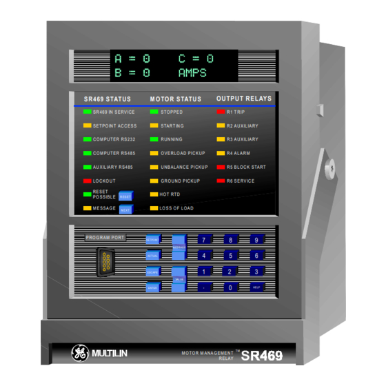
MOTOR MANAGEMENT RELAY
Brand:
Multilin
| Category:
Relays
| Size: 4 MB
Table of Contents
Table of Contents
2
1 Introduction
9
Overview
9
Order Information
10
Sr469 Specifications
11
2 Installation
15
Mechanical
15
Description
15
Product Identification
16
Installation
16
Unit Withdrawal and Insertion
18
Terminal Locations
19
Electrical
20
Typical Wiring
22
Control Power
22
Phase Current Inputs
22
Ground Current Input
23
Differential Current Inputs
24
Voltage Inputs
25
Digital Inputs
25
Analog Inputs
26
Analog Outputs
26
Rtd Sensor Connections
27
Output Relays
30
Drawout Indicator
31
Rs485 Communications Ports
31
Typical 2 Speed Motor Wiring
32
Dielectric Strength Testing
33
3 Sr469 Operation
34
Overview
34
Sr469 Faceplate
34
Display
35
Led Indicators
35
Rs232 Program Port
36
Keypad
37
Entering Alphanumeric Text
37
Entering +/- Signs
37
Setpoint Entry
38
4 Setpoint Programming
40
Overview
40
Trips / Alarms/ Blocks Defined
40
Relay Assignment Practices
41
Setpoint Message Map
42
S1 Sr469 Setup
45
Preferences
45
Serial Ports
45
Real Time Clock
46
Default Messages
46
Message Scratchpad
47
Clear Data
48
Installation
49
S2 System Setup
50
Current Sensing
50
Voltage Sensing
51
Power System
51
Serial Communication Control
52
Reduced Voltage
52
S3 Digital Inputs
53
Access Switch
54
Test Switch
54
Emergency Restart
54
Remote Reset
54
Starter Status
55
Assignable Digital Inputs
55
Digital Input Function: Remote Alarm
56
Digital Input Function: Remote Trip
56
Digital Input Function: Speed Switch Trip
57
Digital Input Function: Load Shed Trip
57
Digital Input Function: Pressure Switch Alarm
57
Digital Input Function: Pressure Switch Trip
58
Digital Input Function: Vibration Switch Alarm
58
Digital Input Function: Vibration Switch Trip
58
Digital Input Function: Digital Counter
59
Digital Input Function: Tachometer
60
Digital Input Function: General Switch A-D
61
Digital Input Function: Capture Trace
61
Digital Input Function: Simulate Pre-Fault
61
Digital Input Function: Simulate Fault
61
Digital Input Function: Simulate Pre-Fault
62
S4 Output Relays
63
Force Output Relay
63
S5 Thermal Model
65
Sr469 Thermal Model
65
Overload Curve Setup
66
Unbalance Bias
75
Motor Cooling
76
Hot/Cold Curve Ratio
77
Rtd Bias
77
S6 Current Elements
79
Short Circuit
79
Overload Alarm
80
Mechanical Jam
80
Undercurrent
81
Current Unbalance
82
Ground Fault
83
Phase Differential
84
S7 Motor Starting
85
Acceleration Timer
85
Start Inhibit
85
Jogging Block
86
Restart Block
87
S8 Rtd Temperature
88
Rtd Types
88
Rtd S 1-6
89
Rtd 1-6
89
Rtd S 7 - 10
89
Rtd 7 - 10
90
Rtd 11
91
Rtd 12
91
Open Rtd Sensor
93
Rtd Short/Low Temp
93
S9 Voltage Elements
94
Undervoltage
94
Overvoltage
95
Phase Reversal
95
Frequency
96
S10 Power Elements
97
Power Measurement Conventions
97
Power Factor
98
Reactive Power
99
Underpower
100
Reverse Power
101
Torque Setup
101
Over Torque Setup
102
S11 Monitoring
102
Trip Counter
102
Starter Failure
103
CURRENT, K W , Kvar, Kva DEMAND
105
Pulse Output
106
S12 Analog I/O
108
Analog Outputs 1-4
108
Analog Inputs 1-4
110
Analog in Diff 3-4
111
S13 Sr469 Testing
115
Pre-Fault Setup
115
Fault Setup
116
Test Output Relays
116
Test Analog Output
117
Comm Port Monitor
117
Multilin Use Only
118
S14 Two-Speed Motor
119
Speed2 O/L Setup
119
Speed2 Undercurrent
121
Speed2 Acceleration
121
5 Actual Values
122
Overview
122
Actual Values Messages
122
A1 Status
123
Motor Status
123
Last Trip Data
124
Alarm Status
126
Start Blocks
127
Digital Inputs
128
Real Time Clock
128
A2 Metering Data
129
Current Metering
129
Temperature
130
Voltage Metering
131
Speed
131
Power Metering
132
Torque Alarm Message
132
Demand Metering
133
Analog Inputs
133
Phasors
134
A3 Learned Data
136
Motor Starting
136
Average Motor Load
136
Rtd Maximums
137
Analog in Min/Max
138
A4 Maintenance
139
Trip Counters
139
General Counters
140
Timers
140
A5 Event Recorder
142
Event01 -Event40
142
A6 Product Info
143
Sr469 Model Info
144
Calibration Info
144
Diagnostics
145
Diagnostic Messages for Operators
145
Flash Messages
146
6 Communications
149
Electrical Interface
149
Protocol
149
Modbus Rtu Protocol
149
Data Frame Format and Data Rate
149
Data Packet Format
150
Error Checking
151
Timing
152
Supported Modbus Functions
152
Function Codes 01 and 02 - Read Relay Coil and Digital Input Status
153
Function Codes 03 and 04 - Read Setpoints and Actual Values
155
Function Code 05 - Execute Operation
156
Function Code 06 - Store Single Setpoint
157
Function Code 07 - Read Device Status
158
Function Code 08 - Loopback Test
159
Function Code 16 - Store Multiple Setpoints
160
Function Code 16 - Performing Commands
161
Error Responses
162
Memory Map
163
Memory Map Information
163
User Definable Memory Map Area
163
Event Recorder
163
Waveform Capture
164
7 Testing
219
Test Setup
219
Secondary Injection Test Setup
219
Hardware Functional Testing
220
Phase Current Accuracy Test
220
Voltage Input Accuracy Test
220
Ground (1A/5A) and Differential Accuracy Test
221
Multilin 50:0.025 Ground Accuracy Test
222
Rtd Accuracy Test
222
Digital Inputs and Trip Coil Supervision
224
Analog Inputs and Outputs
224
Output Relays
226
Additional Functional Testing
227
Overload Curve Test
227
Power Measurement Test
228
Unbalance Test
229
Voltage Phase Reversal Test
230
Short Circuit Test
231
8 Pc Program
233
Installation/Upgrade
233
Configuration
234
Upgrading Relay Firmware
235
Figure 8-4 Upgrading Relay Firmware
235
Creating a New Setpoint File
236
Figure 8-5 Creating a New Setpoint File
236
Editing a Setpoint File
237
Figure 8-6 Editinga Setpoint File
237
Downloading a Setpoint File to the Sr469
238
Figure 8-7 Downloading a Setpoint File to the Sr469
238
Upgrading Setpoint File to New Revision
239
Figure 8-8 Upgrading Setpoint File to New Revision
239
Printing
240
Figure 8-9 Printing
240
Trending
241
Figure 8-10 Trending
242
Waveform Capture
243
Figure 8-11 Waveform Capture
244
Phasors
245
Figure 8-12 Phasors
245
Event Recording
246
Figure 8-13 Event Recording
247
Advertisement
Advertisement
Related Products
Multilin 139 series
Multilin FB600
Multilin FB600E
Multilin PROTECT 4A-120
Multilin PROTECT 4A-240
Multilin Categories
Relays
More Multilin Manuals
Login
Sign In
OR
Sign in with Facebook
Sign in with Google
Upload manual
Upload from disk
Upload from URL