Table of Contents
Advertisement
Advertisement
Table of Contents

Related Manuals for Multilin PROTECT 4A-120


Summary of Contents for Multilin PROTECT 4A-120
- Page 1 MOTOR PROTECTION RELAY INSTRUCTION MANUAL...
- Page 2 INSTRUCTION MANUAL MOTOR PROTECTION RELAY PATENTS U.S. 4,241,336 4,224,651 CANADA 1, 1 30,383 COPYRIGHT 1982, 1986, 1988 MULTILIN ALL RIGHTS RESERVED 215 Anderson Ave., PO Box 2700 Markham, Ontario, Canada L3P 4C7 Tel: (905) 294-6222 Fax: (905) 294-8512...
-
Page 3: Table Of Contents
TABLE OF CONTENTS 1. INTRODUCTION Motor Protection Requirements ........... 1 Protect 4A Features ..............3 Typical Applications ..............4 Order Code .................. 5 Technical Specifications .............. 6 2. INSTALLATION Physical Dimensions ..............7 Mounting ..................9 External Wiring ................10 Control Power ................ -
Page 4: Introduction
1. INTRODUCTION 1.1 MOTOR PROTECTION REQUIREMENTS Three phase AC motors have become the workhorse of mod- ern industry. Although motors are generally reliable devices, many different causes ranging from abnormal conditions to op- erator abuse can result in premature failure. Newer motors also tend to be designed much closer to the normal operation limits allowing less margin for abuse. - Page 5 FIGURE1-1 PROTECT 4A TYPICAL SYSTEM CONNECTION...
-
Page 6: Protect 4A Features
1.2 PROTECT 4A FEATURES A microcomputer housed in a rugged, industrial package al- lows the Protect 4A to provide accurate, economical protection in a unit that will outlast the life of the motor. Since many new factories are using programmable controllers as automation in- creases, a 4-20mA output of motor current is also provided elimi- nating the need for an additional transducer. -
Page 7: Typical Applications
1.3 TYPICAL APPLICATIONS Versatile features make the Protect 4A an ideal choice in a wide range of motor applications. It should be considered for these and other typical uses: Basic protection on low and medium voltage motors. The lowest horsepower selected for protection in an installa- tion will depend on frequency of motor failure. -
Page 8: Order Code
1.4 ORDER CODE TABLE 1-2 RELAY ORDER CODE RELAY PROTECT 4A — 120 PART NO. DESCRIPTION PROTECT 4A Standard relay — 120 120 VAC control voltage — 240 240 VAC control voltage PHASE SENSING CURRENT TRANSFORMERS Any standard 5 amp secondary 5 VA or greater CT can be used. -
Page 9: Technical Specifications
1.5 TECHNICAL SPECIFICATIONS TABLE 1-3 TECHNICAL SPECIFICATIONS FULL LOAD CURRENT MOTOR AMPS OUTPUT 50-100% PHASE CT RATING OUTPUT CURRENCY: 4 mA = 0 AMPS INPUT: 0-8 TIMES MAXIMUM RANGE 20 mA = PHASE CT RATING CURRENT ACCURACY: LINEAR ±5% FULL SCALE FREQUENCY: 48-62 Hz, 3 PHASE SINUSOID MAXIMUM LOAD... -
Page 10: Installation
Phase CTs with 1 amp or 5 amp secondaries should be used. These can be standard CTs which are user supplied. Dimen- sions for CTs available from Multilin are shown in figure 2.2. If zero sequence ground fault detection is required, the appropri- ate ground fault CT shown in figure 2-3 must be installed. - Page 11 FIGURE 2-2 PHASE CT DIMENSIONS FIGURE 2-3 GROUND FAULT CT DIMENSIONS...
-
Page 12: Mounting
2.2 MOUNTING Normally the Protect 4A relay will be mounted on a panel or motor control center door so that the indicators can be viewed and the reset button is directly accessible. A square cutout is made in the door as shown in fig. 2-1. The relay is then placed in the cutout and two mounting brackets are installed to hold it in place as shown in fig 2-4. -
Page 13: External Wiring
2.3 EXTERNAL WIRING A typical wiring diagram for the Protect 4A relay is shown in figure 2-5. Connections are made to the terminal board pro- vided which is then plugged onto the Protect 4A relay. Protect 4A relays are interchangeable and can be quickly replaced by a standard spare unit regardless of the motor current range. -
Page 14: Control Power
2.4 CONTROL POWER Control power must be applied to the Protect 4A relay before energizing the motor for correct operation. Supply voltage can be selected as 120VAC or 240VAC by a selector switch on the power supply board. The supply voltage for which the relay is set will be clearly mark- ed on the wiring diagram label attached to the outside of the relay. -
Page 15: Trip Contacts
2.5 TRIP CONTACTS One set of form C normally open/normally closed contacts are provided for switching up to 240VAC, 10 amps, 360VA which should be adequate for most loads. Silver cadmium oxide con- tacts are provided because of their ability to withstand high in- rush inductive loads. - Page 16 connection to terminals 5 and 6. A no sensor detector will pre- vent the relay from tripping. Alternately, a jumper can be placed across these two terminals. The Protect 4A relay is not suit- able for use with RTDs (resistance temperature detectors). If no thermistor is used, put a jumper between terminals 5 and 6 to prevent nuisance tripping from noise.
-
Page 17: Programmable Controller Output
2.7 PROGRAMMABLE CONTROLLER OUT- In many installations an output of motor current into a program- mable controller is desirable. Terminals 4 (+ VE) and 5 (-VE) provide a DC output of 4-20mA proportional to motor current. The 20mA output is obtained at the rated CT ratio. For exam- ple, if a 600:5 CT is used, at 600 Amps the output would be 20mA. -
Page 18: Field Options - Auto Reset
FIGURE 2-9 FIELD PROGRAMMABLE OPTIONS 2.9.1 AUTO RESET Normally a Protect 4A relay will only reset after a trip by push- ing the reset button. If it is required to automatically reset when- ever a trip occurs, set switch S306 on. The relay will automatically reset about 5 seconds after tripping. -
Page 19: Mechanical Jam
2.9.2 MECHANICAL JAM Overloads will normally cause a trip according to the overload curves of fig. 3-2. In some situations it may be desirable to pro- tect associated mechanical equipment against a jam while runn- ing. Setting switch S303 off will cause the relay to trip whenever the current rises above 3 times the FULL LOAD—AMPS con- trol setting for one second while the motor is running The Protect 4A automatically defeats mechanical jam during... -
Page 20: Single Phase Defeat
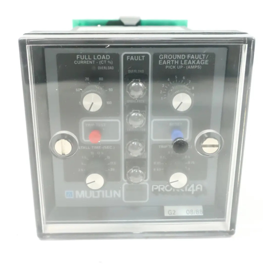
This scheme is not suitable for solidly grounded systems since any motor which develops a ground fault should be shut down immediately due to the high current that can flow. Once the ground fault indicator is set it can only be reset by pressing the reset button. - Page 21 FIGURE 3-1 FRONT PANEL LAYOUT...
-
Page 22: Setup And Use
3. SETUP AND USE 3.1 CONTROL AND INDICATORS NAME FUNCTION FULL LOAD CONTROL Sets the maximum average RMS motor current at which overload pickup occurs. Calibrated in % CT rated amps. STALL TIME Selects one of eight overload time curves based on stall times at 6 times inrush current. -
Page 23: Full Load Control
3.2 FULL LOAD CONTROL The full load control is calibrated in % of phase CT rated amps. It should be set to the maximum load rating of the motor being protected. For example, a setting of 75% with 100:5 phase CTs corresponds to a motor full load current of 75 amps. - Page 24 FIGURE 3-2 TIME/OVERLOAD CURVES P4A STANDAR D OVERLOAD CURVES 1 0 00 0 0 1 00 0 0 10 0 0 1 0 0 1 .0 0 0 . 1 0 1 .0 0 1 0 0 1 0 0 0 FU L L L OA D OVERLOAD FACTOR C O N TR OL S E TTI N G...
- Page 25 TABLE 3-2 TIME/OVERLOAD CHARACTERISTIC TRIP TIME VS. OVERLOAD (SECONDS) Multiples of Full Load Stall Time Setting 1.25 5.8 10.9 29.2 7.9 11.7 21.9 58.4 7.5 10.9 17.5 32.8 87.6 10 14.6 23.3 43.7 12.5 9.1 12.5 18.2 29.2 54.7 10.9 15 21.8 35.0 65.6 17.5 12.7 17.5 25.5 40.8 76.5...
-
Page 26: Stall Time Control
3.3 STALL TIME CONTROL One of eight different time/overload curves can be selected by the stall time control to closely match the thermal characteris- tics of the motor. If curve data is available from the motor manufacturer the next lowest curve from fig. 3-2 should be se- lected and the stall time control set accordingly. -
Page 27: Ground Fault (Earth Leakage) Level Control
3.4 GROUND FAULT (EARTH LEAKAGE) LEVEL CONTROL Aging or overheating may cause the insulation of the stator win- dings to degrade until a point of the stator winding touches the metal stator slot or the insulation becomes carbonized. This pro- vides a low impedance path from the supply to ground and back to the source resulting in very high currents on a solidly grounded system. -
Page 28: Ground Fault (Earth Leakage) Time Delay Control
3.5 GROUND FAULT (EARTH LEAKAGE) TIME DELAY CONTROL In systems with several levels of ground fault (earth leakage) detection, time coordination is required for satisfactory opera- tion. If ground fault protection is used on a bus, each motor must have a shor ter time delay than the bus fault detector or a fault in any motor will shut down the whole bus. -
Page 29: Single Phase Detection
3.6 SINGLE PHASE DETECTION Under normal balanced conditions the stator current in each of the three motor phases is equal and the rotor current is just sufficient to provide the turning torque. When the stator cur- rents are unbalanced, a much higher current is induced in the rotor because it has a much lower impedance to this negative sequence current component. -
Page 30: Thermistor Trip Detection
3.7 THERMISTOR TRIP DETECTION Insulation breakdown of the stator windings due to overheating is the main cause of motor failure under overload conditions. Heat buildup in the rotor can be very rapid but the large ther- mal mass of the motor prevents direct detection by tempera- ture sensors embedded in the stator slots soon enough to prevent damage. -
Page 31: Reset/Test Button
3.8 RESET/TEST BUTTON When a fault condition causes the Protect 4A relay to trip, the red fault light will come on and the fault condition will remain latched. If control power is lost or re-applied the relay will retain the state and fault indications present when control power was removed. -
Page 32: Motor Amps Output
3.9 MOTOR AMPS OUTPUT An output of the average RMS current in the three motor phases is provided for connecting to a programmable controller. Unlike conventional schemes which give an indication of only one phase current, the Protect 4A relay can monitor all 3 phase cur- rents simultaneously without the need for additional current transformers. -
Page 33: Fault Diagnosis
3.10 FAULT DIAGNOSIS Four fault indicators as well as READY/FAULT status lights are provided to display the relay state and cause of fault after trip. Table 3-3 lists probable causes of trip and corrective measures required for various fault indicators. TABLE 3-3 PROTECT 4 FAULT FINDER... -
Page 34: Relay Testing
4. RELAY TESTING 4.1 COMMISSIONING TESTS Prior to applying power at a new installation, system operation can be verified by injecting current through the phase CTs. If a 3 phase current injection set is available it would be connected as shown in figure 2-5 in place of the 3 phase supply and using a short between the 3 phases in place of the motor. - Page 35 FIGURE 4-1 SINGLE PHASE INJECTION TESTING FIGURE 4-2 100 AMP CURRENT SOURCE...
-
Page 36: Overloads
4.2 OVERLOADS Set the FULL LOAD — AMPS control to the desired pickup cur- rent and gradually increase the phase current through the phase CTs. With current applied below the full load pickup point the overload indicator light will be off. When the pickup current is reached the light will flash. -
Page 37: Single Phasing
When checking the time/over current curves for accuracy, it must be remembered that previous overloads will shorten the time available since the internal memory is partially full to simulate motor heating. Before performing timing tests, ensure that full memory capacity is available by: removing and re-applying control power. -
Page 38: Ground Fault/Earth Leakage
4.4 GROUND FAULT/EARTH LEAKAGE When a ground fault occurs on a three phase system, the core balance CT will pick up a sine wave current at the system fre- quency. Consequently, to test this protection feature, pass a wire through the separate ground fault CT and apply a single phase current. - Page 39 FIGURE 4-3 GROUND FAULT/EARTH LEAKAGE TEST...
-
Page 40: Thermistor
4.5 THERMISTOR A simple 5000 ohm variable resistor connected across termi- nals 5 and 6 can be used to check the operation of the thermis- tor circuit as shown in Fig. 4-4. For low resistance values the PROTECT 4A remains untripped. At approximately 3000 ohms the relay will trip. -
Page 41: Ma Output
4.6 4-20 mA OUTPUT Connect a DC milliammeter to terminals 4 (+ ve) and 5 (- ve). With no input current the meter should read zero. Apply a balanc- ed three phase signal through the current transformers equal to the rated CT current (e.g. 100 amps into 100:5 CTs should give a current reading of 20 mA). -
Page 42: Routine Maintenance Verification
4.7 ROUTINE MAINTENANCE VERIFICATION A front panel self test feature is provided so that proper opera- tion of the relay and its indicators can be verified. If this test button is pushed while a motor is running the motor should shut down with the 4 fault indicators set. -
Page 43: Problem Troubleshooting
4.8 PROBLEM TROUBLESHOOTING TABLE 4-1 PROBLEM TROUBLESHOOTING SYMPTOM PROBABLE CAUSE ACTION Periodic – Overload surges – Defeat mechanical jam. Overload during running. Tripping – Incorrect run curve. – Use run curve with longer trip time (higher stall setting). – Previous overloads –... - Page 44 FIGURE 5-1 HARDWARE BLOCK DIAGRAM...
-
Page 45: Theory Of Operation
5. THEORY OF OPERATION 5.1 HARDWARE The Protect 4A is able to provide many protection features at low cost through the use of a powerful single chip microcomputer as shown in block diagram of figure 5-1 and the schematic in- sert. - Page 46 FIGURE 5-2 SINGLE PHASE DETECTION FIGURE 5-2a 3 PHASES, BALANCED CONDITION FIGURE 5-2b SINGLE PHASE CONDITION...
- Page 47 All front panel and option switches are monitored and stored in the microprocessor for use by various parts of the program. Indicators and the output relay are strobed under program con- trol as required. Since these are activated by pulse action, power is conserved and the relay returns to the state before loss of power whenever power is reapplied Reliable operation of the microprocessor under erratic or tran-...
-
Page 48: Firmware
5.2 FIRMWARE All mathematical computations and logical operations are per- formed by a program stored in the microcomputer. Execution flow of the routines is shown in the firmware block diagram of fig. 5-3. An initialize routine ensures that the system always comes up in the same state when first powered on. - Page 49 FIGURE 5-3 FIRMWARE BLOCK DIAGRAM...
- Page 50 MULTILIN RELAY WARRANTY Multilin warrants each relay it manufactures to be free from defects in material and workmanship under nor- mal use and service for a period of 24 months from date of shipment from factory. In the event of a failure covered by this warranty,...
- Page 51 MOTOR PROTECTION 215 Anderson Ave., P.O. Box 2700 Markham, Ontario, Canada L3P 4C7 Tel: (905) 294-6222 Fax: (905) 294-8512 Made in Canada PART NO. P4A-M01/94V...
Need help?
Do you have a question about the PROTECT 4A-120 and is the answer not in the manual?
Questions and answers