Table of Contents
Advertisement
Quick Links
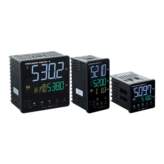
SuperNova PD500 PID Process & Temperature Controllers
Instruction Manual
1/16, 1/8, and 1/4 DIN Auto-Tuning PID Process & Temperature Controllers
•
Thermocouple and RTD Inputs
•
DC Voltage and Current Inputs (1-5 V, 0-5 V, 0-10 V, 0-50 mV, 0-100 mV; 4-20 mA with Resistor)
•
250 Ω Resistor(s) Included Standard
•
High Accuracy Auto-Tuning PID
•
•
High Durability Front with Hard Plastic Pushbuttons
•
Large Easy to Read 14-Segment PV Display up to 1.1" (29 mm)
•
Input Power 100-240 VAC
Heating, Cooling, and Heating & Cooling Control
•
Primary Control Output Options: 4-20 mA (SCR), Voltage Pulse (SSR), or Relay
•
Secondary Control Output Relay Standard on All Models
•
Easily Switch Between Auto and Manual Control Modes
•
Up to 2 Alarm Relays & 4-20 mA Retransmit Outputs
•
Remote Set Value 1-5 V Input Option (4-20 mA with External Resistor)
•
•
Digital Input Set Value Selection
•
RS-485 Serial Communications Option
•
Modbus® RTU/ASCII Communications
•
Mini-USB Port Standard
•
FREE Programming and Monitoring Software
1/16, 1/8, 1/4 DIN Sizes Available
•
Shallow Depth Case Extends Only 2.5" (63 mm) Behind Panel
•
IP65 Fronts
•
UL & C-UL Recognized Process Control Equipment, Electrical - Component
•
PRECISION DIGITAL CORPORATION
233 South Street • Hopkinton MA 01748 USA
Tel (800) 343-1001 • Fax (508) 655-8990
www.predig.com
Advertisement
Table of Contents

Related Manuals for Precision Digital Corporation SuperNova PD500


Summary of Contents for Precision Digital Corporation SuperNova PD500
- Page 1 SuperNova PD500 PID Process & Temperature Controllers Instruction Manual 1/16, 1/8, and 1/4 DIN Auto-Tuning PID Process & Temperature Controllers • Thermocouple and RTD Inputs • DC Voltage and Current Inputs (1-5 V, 0-5 V, 0-10 V, 0-50 mV, 0-100 mV; 4-20 mA with Resistor) •...
- Page 2 SuperNova PD500 PID Process & Temperature Controllers Instruction Manual Disclaimer The information contained in this document is subject to change without notice. Precision Digital makes no representations or warranties with respect to the contents hereof and specifically disclaims any implied warranties of merchantability or fitness for a particular purpose.
-
Page 3: Table Of Contents
SuperNova PD500 PID Process & Temperature Controllers Instruction Manual Table of Contents Introduction ......................6 Abbreviations ....................6 General Controller Term Descriptions ............6 Range and Scale Descriptions ..............6 Engineering Unit Descriptions ..............7 Ordering Information ..................8 Enclosures ...................... 9 Accessories .................... - Page 4 SuperNova PD500 PID Process & Temperature Controllers Instruction Manual G.COM Parameter Details ................. 33 Sub Relay Group (G.SUB) ................. 34 G.SUB Parameter Details ................36 Transmit & Remote Group (G.TRS) ............37 G.TRS Parameter Details ................38 Alarm Group (G.ALM) ................39 G.ALM Parameter Details ................
- Page 5 SuperNova PD500 PID Process & Temperature Controllers Instruction Manual Table of Figures Figure 1. Panel Cutout Dimensions ..............16 Figure 2. PD510 Mounting Bracket Installation ..........16 Figure 3. PD520 and PD530 Mounting Bracket Installation ......16 Figure 4. Controller Dimensions ..............17 Figure 5.
-
Page 6: Introduction
Instruction Manual Introduction The SuperNova PD500 Series of PID Process & Temperature Controllers is a complete line of PID and on/off controllers. Available in popular 1/4, 1/8, and 1/16 DIN sizes, and with a shallow depth behind panel of only 2.5"... -
Page 7: Engineering Unit Descriptions
SuperNova PD500 PID Process & Temperature Controllers Instruction Manual Engineering Unit Descriptions During the programming of the controller, there are two types of engineering units referred to, EU, and EUS. The value in engineering units according to the input range. -
Page 8: Ordering Information
SuperNova PD500 PID Process & Temperature Controllers Instruction Manual Ordering Information Model Number DIN Size Main Control Output Additional Features PD510-A 1/16 4-20 mA (SCR) Relay Control Output, 2 Alarm Relays PD510-A-CD 1/16 4-20 mA (SCR) Relay Control Output, 2 Alarm Relays, RS-485, 2 Digital Inputs... -
Page 9: Enclosures
SuperNova PD500 PID Process & Temperature Controllers Instruction Manual Enclosures Accessories Model Description 250 Ω 0.1% Precision Resistor for PDX-RES2 SuperNova 4-20 mA Input PDA7485-I RS-232 to RS-485 isolated converter PDA8485-I USB to RS-485 isolated converter PD9501 Multi-function calibrator PDA-LH... -
Page 10: Specifications
SuperNova PD500 PID Process & Temperature Controllers Instruction Manual Specifications Process Input Except where noted all specifications apply to Process Input Voltage or current (with external Selection resistor) operation at +25°C. General Process Input 1-5 V (4-20 mA), 0-5 V, 0-10 V, 0-50 mV, 0-100 mV External 250 Ω... -
Page 11: Temperature Input
SuperNova PD500 PID Process & Temperature Controllers Instruction Manual Temperature Input Control Outputs Temperature Control Field programmable for thermocouple Each controller has a main control output Input Selection or RTD Outputs and a secondary control relay output for two directions of control. The secondary... -
Page 12: Alarm Relay Outputs
SuperNova PD500 PID Process & Temperature Controllers Instruction Manual Alarm Relay Outputs 4-20 mA Retransmit Output Function Function Programmable for 13 different alarm 4-20 mA linear current output types or off. Scaling Range 0-100% of full scale Number Two alarm relays standard on all Output Loop 600 Ω... -
Page 13: Modbus® Rtu Serial Communications
SuperNova PD500 PID Process & Temperature Controllers Instruction Manual SuperNova TCS Software Modbus® RTU Serial Communications Availability Download directly from www.predig.com/download_software Communica- EIA RS-485 standard, 2-wire half-duplex Operating Microsoft Windows 7/8/10 ® ® tion Method with grounded, shielded cable System... -
Page 14: Compliance Information
SuperNova PD500 PID Process & Temperature Controllers Instruction Manual Compliance Information Safety Information Safety • Read complete instructions prior to installation UL & C-UL USA & Canada and operation of the controller. Recognized Process Control Equipment, Electrical – • Install outdoors only with appropriate protection. -
Page 15: Operation & Care Notes
SuperNova PD500 PID Process & Temperature Controllers Instruction Manual Operation & Care Notes Installation • Please do not clean the controller with organic There is no need to remove the controller from its solvents such as alcohol, benzene, etc. Clean it case to complete the installation, wiring, and with neutral detergents. -
Page 16: Panel Mounting Instructions
SuperNova PD500 PID Process & Temperature Controllers Instruction Manual Panel Mounting Instructions • Prepare the appropriate standard DIN panel cutout. Refer to Figure 1. Panel Cutout Dimensions below for more details. Clearance: allow at least 3.5" (88.4 mm) behind •... -
Page 17: Controller Dimensions
SuperNova PD500 PID Process & Temperature Controllers Instruction Manual Controller Dimensions Controller Dimensions Units: in (mm) Dimension PD510 PD520 PD530 48.0 48.0 96.0 48.0 96.0 96.0 63.0 63.0 63.0 Figure 4. Controller Dimensions... -
Page 18: Connections
SuperNova PD500 PID Process & Temperature Controllers Instruction Manual Connections Connectors Labeling The connector labelling diagraph marked on the All connections are made to non-removable controller shows the location of all connectors screw terminal connectors located at the rear of available with requested configuration. -
Page 19: Power Connections
SuperNova PD500 PID Process & Temperature Controllers Instruction Manual Power Connections Power connections are made to two terminals. Figure 11. PD520 & PD530 Signal Connection Figure 8. PD510 Power Connection Relay Connections Each controller has 3 or 4 relay outputs, one or two control relays and 2 alarm relays. -
Page 20: 4-20 Ma Output Connections
SuperNova PD500 PID Process & Temperature Controllers Instruction Manual 4-20 mA Output Connections Remote SV Input Connections Connections for the 4-20 mA retransmit output are Connections to the remote set value input are made made to the connector terminals labeled mA OUT. -
Page 21: Controller Operation
SuperNova PD500 PID Process & Temperature Controllers Instruction Manual Controller Operation Change Control Set Value (SP) The Set Value can be easily changed to a new control The controller can accept thermocouple, RTD, set point by pressing the SET key, and using the UP, voltage, or current inputs (4-20 mA with an external DOWN, and SHIFT keys to enter the new set point. -
Page 22: Front Panel Buttons And Status Indicators
SuperNova PD500 PID Process & Temperature Controllers Instruction Manual Front Panel Buttons and Status Indicators Figure 22. Front Panel Buttons and Indicators... -
Page 23: Setup And Programming
SuperNova PD500 PID Process & Temperature Controllers Instruction Manual Setup and Programming Group Group General Description Display Name There is no need to recalibrate the controller G.SV Select active Set Values and when first received from the factory. Value Set Value limits. -
Page 24: Programming The Controller
SuperNova PD500 PID Process & Temperature Controllers Instruction Manual Programming the Controller In addition to setting this parameter directly, digital inputs may be used to select from SV1 and SV4 or The following section defines the parameters in each the remote Set Value input (REM). -
Page 25: Input Group (G.in)
SuperNova PD500 PID Process & Temperature Controllers Instruction Manual Input Group (G.IN) Input Type Display Range -328 to 2498°F The Input Group includes parameters to select the input type, define display units, and scale a process -200 to 1370°C input. -
Page 26: G.in Parameter Details
SuperNova PD500 PID Process & Temperature Controllers Instruction Manual Scale High Limit (SL-H) Filter Time (FILT) Set the display value for the desired units when at the The input noise filter is used to compensate for noise high limit of the selected mA, VDC, or mVDC input of unsteady readings of the input. -
Page 27: Output Group (G.out)
SuperNova PD500 PID Process & Temperature Controllers Instruction Manual Output Group (G.OUT) Heating & Cooling Control Mode When OUT2 is set to either ONOF or PID, the The Output Group includes parameters used to controller will automatically enter heating and cooling configure the general operation of the control outputs. -
Page 28: Output Limit High (Ol-H) And Low (Ol-L)
SuperNova PD500 PID Process & Temperature Controllers Instruction Manual Hysteresis, Heating (HYS) and When both CNT1 and CNT2 are used, EO and EOC are generated as follows. Hysteresis, Cooling (HYSC) HOUT Emergency Output when Control Output 1 When using on/off control, the hysteresis sets the... -
Page 29: G.out Parameter Details
SuperNova PD500 PID Process & Temperature Controllers Instruction Manual G.OUT Parameter Details Default Parameter Setting Range Unit Parameter Display Condition Value CNT1 ONOF, PID CNT2 NONE, ONOF, PID NONE OUT2 control mode CNT2 is set O.ACT REV, DIR to NONE... -
Page 30: Settings Group (G.set)
SuperNova PD500 PID Process & Temperature Controllers Instruction Manual Settings Group (G.SET) Power-On Operation Mode (POOM) The Settings Group includes parameters for general controller setup, such as power-on operation, The controller can be programmed to enter RUN or resetting to factory default settings, or locking STOP mode when it powers on. -
Page 31: G.set Parameter Details
SuperNova PD500 PID Process & Temperature Controllers Instruction Manual EEPROM Lock (E2P.L) System Data (SYS.D) The programmed settings of the controller are stored This parameter displays system data useful to the in two types of hardware memory, short-term use factory for troubleshooting. -
Page 32: Communication Group (G.com)
SuperNova PD500 PID Process & Temperature Controllers Instruction Manual Communication Group (G.COM) Parity Bit (PRI) Select if parity bit function as none (NONE), even The Communication Group includes parameters for configuring RS-485 serial communications. The (EVEN), or odd (ODD) parity. -
Page 33: G.com Parameter Details
SuperNova PD500 PID Process & Temperature Controllers Instruction Manual G.COM Parameter Details Default Parameter Setting Range Unit Parameter Display Condition Value PCK, PCKS, ASCI, RTU 4.8K, 9.6K, 14.4K, 19.2K, 9.6K 38.4K, 57.6K NONE, EVEN, ODD NONE STOP 1 or 2... -
Page 34: Sub Relay Group (G.sub)
SuperNova PD500 PID Process & Temperature Controllers Instruction Manual Sub Relay Group (G.SUB) Alarm ON Time Delay (An.ND) When an alarm condition occurs, the alarm will turn The Sub Relay Group is used to assign alarms to the on only after the ON time delay. Set the ON time Sub relays and set relay controls such as on and off delay in seconds. - Page 35 SuperNova PD500 PID Process & Temperature Controllers Instruction Manual Alarm Latch (An.LT) Loop Break Alarm Fail-Safe (LB.EC) The latch function is used to hold the alarm output The sub output relays are type A electromechanical state even after the alarm condition has been cleared relays.
-
Page 36: G.sub Parameter Details
SuperNova PD500 PID Process & Temperature Controllers Instruction Manual G.SUB Parameter Details Default Parameter Setting range Unit Parameter Display Condition Value SUB1 NONE, ALM1, ALM2, ALM3, ALM1 ALM4, LBA SUB2 ALM2 SUB3 ALM3 PD510: Only when the OUT2 control type parameter is set to NONE. -
Page 37: Transmit & Remote Group (G.trs)
SuperNova PD500 PID Process & Temperature Controllers Instruction Manual Transmit & Remote Group (G.TRS) Retransmit Adjustment High (T-AH) and Low (T-AL) The Transmit and Remote Group is used to configure the 4-20 mA retransmission output as well as the The Retransmit Adjustment High (T-AH) and 4-20 mA remote SV input. -
Page 38: G.trs Parameter Details
SuperNova PD500 PID Process & Temperature Controllers Instruction Manual G.TRS Parameter Details Default Parameter Setting range Unit Parameter Display Condition Value RET.T PV, SV, MV Models with RET option only. T-SH FR.L - FR.H (Note 2) EU 100 % Models with RET option only and SL.L - SL.H (Note 3) -
Page 39: Alarm Group (G.alm)
SuperNova PD500 PID Process & Temperature Controllers Instruction Manual Alarm Group (G.ALM) An.TY Alarm Name Absolute Standby Value or The Alarm Group contains parameters to establish Deviation alarm conditions for up to four alarms. These alarms Alarm may be assigned to the SUB1 or SUB2 alarm output... -
Page 40: Figure 27. Alarm Operation Description Table
SuperNova PD500 PID Process & Temperature Controllers Instruction Manual An.TY Alarm Name Alarm Operation Absolute Standby Value or Deviation Alarm Alarm off High absolute Absolute High absolute with standby sequence Low absolute Absolute Low absolute with standby sequence High deviation... -
Page 41: Figure 28. High Absolute Alarm Operation
SuperNova PD500 PID Process & Temperature Controllers Instruction Manual Alarm Number n Latch Status Alarm Operation Examples (An.LS) High Absolute Alarm Operation An.LS is the alarm latch reset function, where n can The example below illustrates the operation of a high be any of alarms 1, 2, 3, or 4. -
Page 42: Figure 32. Loop Break Alarm (Lba) Operation In Reverse Action Mode
SuperNova PD500 PID Process & Temperature Controllers Instruction Manual Loop Break Detection Time (LB.TM) The loop break detection time is usually set to about twice the value of PID coefficient 1. When auto- tuning is executed, the LB.TM value is automatically set to twice the PID coefficient 1 value. -
Page 43: G.alm Parameter Details
SuperNova PD500 PID Process & Temperature Controllers Instruction Manual G.ALM Parameter Details Default Parameter Setting range Unit Parameter Display Condition Value RET.T PV, SV, MV Models with RET option only. A1.TY 0 - 13 G.SUB parameter SUBx is ALM1 AL-1 Absolute: EU (0.0 - 100.0) %... -
Page 44: Control Group (G.ctl)
SuperNova PD500 PID Process & Temperature Controllers Instruction Manual Control Group (G.CTL) The Control Group contains parameters to begin and adjust auto-tuning, set manual PID parameters, and perform basic control functions such as set value ramp up and down behavior. -
Page 45: Figure 33. Standard And Low Pv Auto-Tuning Sv
SuperNova PD500 PID Process & Temperature Controllers Instruction Manual Auto-Tuning Mode (AT.MD) Press and hold the front panel keys SET and UP for 3 seconds. There are two types of auto-tuning (AT): standard When auto-tuning process has started, the type and low PV type. -
Page 46: Figure 34. Response Adjustment With Alpha
SuperNova PD500 PID Process & Temperature Controllers Instruction Manual Figure 35. Set Value Ramp Up Figure 34. Response Adjustment with Alpha When the Integral Time (n.I) parameter is set to 0 SV Ramp Up (RM.UP) (OFF), the Alpha (ALPA) parameter value will be set... -
Page 47: G.ctl Parameter Details
SuperNova PD500 PID Process & Temperature Controllers Instruction Manual G.CTL Parameter Details Default Parameter Setting range Unit Parameter Display Condition Value AT.MD STD, LOW G.OUT parameter CNT1 is PID or G.OUT parameter CNT2 is PID. OFF, ON G.OUT parameter CNT1 is PID or G.OUT parameter CNT2 is PID. - Page 48 SuperNova PD500 PID Process & Temperature Controllers Instruction Manual Default Parameter Setting range Unit Parameter Display Condition Value 4.MR -5.0 - 105.0 50.0 G.OUT parameter CNT1 is set to PID and 4.I is set to OFF. 4.Pc EUS (0.0 - 100.0) % Note 1 EUS 5.0%...
-
Page 49: Supernova Tcs Software
SuperNova PD500 PID Process & Temperature Controllers Instruction Manual Monitoring SuperNova TCS Software SuperNova TCS software can be used to monitor up The SuperNova line of controllers includes the FREE to 31 SuperNova controllers on a PC. The screenshot SuperNova TCS monitoring and programming below shows SuperNova TCS software monitoring a software. -
Page 50: Running Supernova Tcs The First Time
SuperNova PD500 PID Process & Temperature Controllers Instruction Manual Running SuperNova TCS the First Time The first time SuperNova TCS is run it is necessary to set up the serial communication settings of the program. Click the Add Serial Communications icon in the upper left menu, as identified below. - Page 51 SuperNova PD500 PID Process & Temperature Controllers Instruction Manual Monitoring data saving start Multitrend Starts data logging for the selected units in the Opens the trend graph monitoring screen for all System menu list. connected controllers. Start saving all the monitoring data Starts data logging for all connected units on a port.
-
Page 52: Troubleshooting Tips
SuperNova PD500 PID Process & Temperature Controllers Instruction Manual Troubleshooting Tips Symptom Check/Action No display at all Check power at power terminals. The controller is in STOP mode. Change it to RUN mode by The MV display is blank. holding the shift key for 2 seconds. -
Page 53: Error Messages
SuperNova PD500 PID Process & Temperature Controllers Instruction Manual Error Messages Display Error Type Cause and Action System Data System data error (please contact technical support) Option Data Option data error (please contact technical support) EEPROM EEPROM error (please contact technical support) -
Page 54: Modbus Register Tables
SuperNova PD500 PID Process & Temperature Controllers Instruction Manual Modbus Register Tables Fixed Modbus Tables General Process and Indication, Address 0 - 99 Address D-register Parameter (Only) 40001 9C41 0000 Current PV 40002 9C42 0001 Current set value 40003 9C43... -
Page 55: Control Group (G.ctl), Address 200 - 299
SuperNova PD500 PID Process & Temperature Controllers Instruction Manual Control Group (G.CTL), Address 200 - 299 Address D-register Parameter (Only) 40201 9D09 00C8 AT.MD Auto-tuning mode 40202 9D0A 00C9 Auto-tuning 40205 9D0D 00CC Anti-reset Windup 40206 9D0E 00CD ALPA Alpha PID.N... -
Page 56: Alarm Group (G.alm) Address, 300 - 399
SuperNova PD500 PID Process & Temperature Controllers Instruction Manual Alarm Group (G.ALM) Address, 300 - 399 Address D-register Parameter (Only) 40301 9D6D 012C A1.TY Alarm 1 type 40302 9D6E 012D AL-1 Alarm 1 set value 40303 9D6F 012E A1.DB Alarm 1 deadband... -
Page 57: Sub Relay Group (G.sub), Address 500 - 599
SuperNova PD500 PID Process & Temperature Controllers Instruction Manual SUB Relay Group (G.SUB), Address 500 - 599 Address D-register Parameter (Only) 40501 9E35 01F4 SUB1 Sub1 output type 40502 9E36 01F5 SUB2 Sub2 output type 40503 9E37 01F6 SUB3 Sub3 output type... -
Page 58: Output Group (G.out), Address 800 - 899)
SuperNova PD500 PID Process & Temperature Controllers Instruction Manual Output Group (G.OUT), Address 800 - 899) Address D-register Parameter (Only) 40801 9F61 0320 CNT1 OUT1 output control selection 40802 9F62 0321 CNT2 OUT2 output control selection 40803 9F63 0322 O.ACT... -
Page 59: Modbus Register Bit Information
SuperNova PD500 PID Process & Temperature Controllers Instruction Manual Modbus Register Bit Information Some Modbus registers contain information that is determined on a bit-by-bit basis. The following tables define these register names, what each bit represents, and the values of the settings of each bit. - Page 60 SuperNova PD500 PID Process & Temperature Controllers Instruction Manual ALM_STS (Alarm Status) ERR_STS (Error Status) Description description Status (0) Status (1) Status (0) Status (1) System code error Option code error EEPROM error ADC error Calibration error RIC error HBA on...
-
Page 61: Eu Declaration Of Conformity
EN 61000-3-2:2019, EN 61000-3-3:2013+A1:2019, EN 61000-6-2:2019, EN 61000-6-4:2019, and EN 61010-1:2010+A1:2019 and there were no major technical changes affecting the latest technical knowledge for the products listed above. Product Markings: Signed for and on behalf of Precision Digital Corporation: Name: Jeffrey Peters Company:... - Page 62 SuperNova PD500 PID Process & Temperature Controllers Instruction Manual Contact Precision Digital Technical Support Call: (800) 610-5239 or (508) 655-7300 Fax: (508) 655-8990 Email: support@predig.com Sales Support Call: (800) 343-1001 or (508) 655-7300 Fax: (508) 655-8990 Email: sales@predig.com Place Orders Email: orders@predig.com...
Need help?
Do you have a question about the SuperNova PD500 and is the answer not in the manual?
Questions and answers