
Related Manuals for Q5X QT-AD10


Summary of Contents for Q5X QT-AD10
- Page 1 QT‐AD10 Module Description This document describes the use of the QT‐AD10A/C transmitter. History Rev 1 Original ...
-
Page 2: Table Of Contents
QT‐AD10 Module QT‐AD10 TRANSMITTER MODULE Contents Qt‐AD10 Transmitter Module ........................ 1 FCC Notices: .......................... 3 AD10 Transmitter Module ........................ 6 Introduction .............................. 6 Features .............................. 7 Performance ............................ 7 Design .............................. 7 Working with the AD10 Module ....................... 7 Out‐of‐the‐Box Setup .......................... 7 Storage Mode ............................ 7 Standby Mode ............................ 8 Run Mode .............................. 8 Control and Configuration of Modules ..................... 8 ... -
Page 3: Fcc Notices
QT‐AD10 Module FCC Notices: Information to users: This device complies with Part 15 of the FCC Rules. Operation is subject to the following two conditions: (1.) This device may not cause harmful interference, and (2.) This device must accept any interference received, including interference that may cause undesired operation. : This equipment has been tested and found to comply with the limits for a Class B digital device, pursuant to part 15 of the FCC Rules. These limits are designed to provide reasonable protection against harmful interference in a residential installation. This equipment generates, uses and can radiate radio frequency energy and, if not installed and used in accordance with the instructions, may cause harmful interference to radio communications. However, there is no guarantee that interference will not occur in a particular installation. If this equipment does cause harmful interference to radio or television reception, which can be determined by turning the equipment off and on, the user is encouraged to try to correct the interference by one or more of the following measures: — Reorient or relocate the receiving antenna. — Increase the separation between the equipment and receiver. — Connect the equipment into an outlet on a circuit different from that to which the receiver is connected. — Consult the dealer or an experienced radio/TV technician for help. Warning: Wireless microphone users shall rely on the white space databases in part 15, Subpart H to determine that their intended operating frequencies are available for unlicensed wireless microphone operation at the location where they will be used. Wireless microphone users must register with and check a white space database to determine available channels prior to beginning operation at a given location. A user must re‐check the database for available channels if it moves to another location. Warning: Changes or modifications not expressly approved by Quantum5X Systems Inc, could void the user’s authority to operate the equipment. Warning: This module has been designed to operate with only the supplied integrated antenna or ... - Page 4 This radio transmitter IC:4614A‐QTAD10A / IC:4614A‐QTAD10C has been approved by Innovation, Science and Economic Development Canada to operate with the antenna types listed below, with the maximum permissible gain indicated. Antenna types not included in this list that have a gain greater than the maximum gain indicated for any type listed are strictly prohibited for use with this device. Le présent émetteur radio IC:4614A‐QTAD10A / IC:4614A‐QTAD10C a été approuvé par Innovation, Sciences et Développement économique Canada pour fonctionner avec les types d'antenne énumérés ci‐dessous et ayant un gain admissible maximal. Les types d'antenne non inclus dans cette liste, et dont le gain est supérieur au gain maximal indiqué pour tout type figurant sur la liste, sont strictement interdits pour l'exploitation de l'émetteur. This device operates on a no‐interference, no‐protection basis. Should the user seek to obtain protection from other radio services operating in the same TV bands, a radio licence is required. For further details, consult Innovation, Science and Economic Development Canada’s Client Procedures Circular CPC‐2‐1‐28, Voluntary Licensing of Licence‐Exempt Wireless Microphones in the TV Bands. Ce dispositif fonctionne selon un régime de non‐brouillage et de non‐protection. Si l’utilisateur devait chercher à obtenir une certaine protection contre d’autres services radio fonctionnant dans les mêmes bandes de télévision, une licence radio serait requise. Pour en savoir plus, veuillez consulter la Circulaire des procédures concernant les clients CPC‐2‐1‐28, Délivrance de licences sur une base volontaire pour les microphones sans fil exempts de licence exploités dans les bandes de télévision d’Innovation, Sciences et Développement économique Canada. Antenna / Connector Type Manufacture Connector Type Max Gain ¼λ Wire Antenna Q5X MHF‐4L UHF 0 dBi, 2.45GHz 2dBi Sam Woo Electronics MHF‐4L ‐SSMA SSMA ¼λ Whip Antenna UHF 0 dBi, 2.45GHz 2dBi ...
- Page 5 QT‐AD10 Module RF Exposure Compliance: The QT‐AD10 Module is granted with a modular approval for portable applications. The module is to be used by Quantum5X in their final products without additional FCC/ISED(Innovation, Science and Economic Development Canada) certification if they meet the certification conditions. Module Integration into Host End Products The QT‐AD10 Module Transmitter has been designed by Quantum5X Systems Inc. to be used by Quantum5X as a building block for their wireless audio transmitter products. The module, as designed, is a standalone unit that is ready for integration into final form factor with the limitation for mobile use as specified in RF Exposure compliance. For proper usage of the module, the module integrator must ensure that the input power and input audio signal do not exceed the specified limits as outlined in the specification section. Failure to do so will result in damage to the module. Final product(s) after integration with this module shall be tested to comply with all applicable FCC requirements and Unintentional radiators (FCC section 15.107, 15.109 and ISED ICES‐003) before declaring compliance to Part 15 of the FCC Rules and ISED ICES‐003. The module integrator may not: 1) Alter, modify or remove the module case. 2) Make changes to the Circuit Card Assembly of the module. 3) Remove, change or alter the integrated UHF antenna or the 802.15.4 antenna. Failure to comply with these restrictions will result in violation of the FCC certification. Labeling of the End Products: The modular transmitter must be equipped with either a permanently affixed label. The modular transmitter must be labeled with its own FCC identification number, and, if the FCC identification number is not visible when the module is installed inside another device, then the outside of the device into which the module is installed must also display a label referring to the enclosed module. This exterior label can use wording such as the following: ‘‘Contains Transmitter Module” or ‘‘Contains “. Any similar wording that expresses the same meaning may be used. Below are Sample Module and Product lables that must be used for the Module and the Product. ...
-
Page 6: Ad10 Transmitter Module
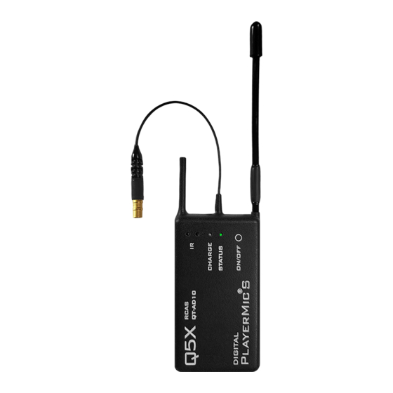
QT‐AD10 Module AD10 Transmitter Module Introduction AD10 series bodypack transmitters deliver impeccable audio quality and RF performance with wide‐ tuning, High Density (HD) mode, and encryption. The transmitter module features durable metal construction, and single pin Lemo connector. The Q5X remote control system is referred to as RCAS, Remote Control Audio System. Q5X pioneered wireless remote control for transmitters in 2009. Since this is a wireless control system, it will work through walls, clothing, uniforms, costumes, etc. and over longer distances than non‐RF types of transmitter control systems on the market. RCAS consists of 4 main components; 1) a QT‐AD10 series transmitter, 2) the MicControl software, 3) the QG‐N3 MicCommander, a network enabled controller, 4) the QG‐H2 MicCommander, a hand held remote control, with USB connectivity The QG‐H2 MicCommander is a handheld, stand alone device used to control the QT‐AD10 series of Q5X audio transmitters, such as the QT‐AD10 PlayerMic. It can also control legacy QT‐5000 transmitters. The QG‐H2 allows the user to view, monitor and make adjustments to any QT‐AD10 transmitter within the control range. It can monitor and/or adjust; the transmitter power state ON or OFF, RF power, UHF frequency, microphone muting and mic gain, groups, transmitter naming, and other operational parameters can be remotely configured using the QG‐H2 without physical access to the transmitter. The QG‐H2 can control up to 32 transmitters as a stand‐alone device. USB connectivity allows the QG‐H2 to be connected to a laptop or PC running Windows 7 and above. This connection allows the use of the MicControl software on the PC to control enhanced features of the transmitters including the ability to name transmitters. Naming transmitters makes it much easier to manage the system, for example instead of looking at a list of serial numbers like 10223 or 20567 you can now name them Player1 or Actor 2 or Joes Mic. The RCAS system can also be networked and uses the network enabled QG‐N3 to remotely control the QT‐AD10 series of transmitters via MicControl software which can be installed on a Windows PC or laptop. Multiple QG‐N3 units can be added to a network to manage large area installations. The MicControl software can control over 300 transmitters for larger installations. The QG‐H2MicCommander operates independently from any other gateway or computer. It communicates one‐to‐one with each transmitter and allows access to all necessary settings through a simple interface. It can over ride any setting made by the MicControl software and vice versa. ... -
Page 7: Features
QT‐AD10 Module Eliminates the need to physically handle the transmitters after they are installed on the user. Remotely turn the transmitter’s On/Off to conserve battery life when not in use. Provides the ability to change the frequency in the event of RF interference. Provides the ability to change the microphone’s gain if the audio is too loud or soft. Features Performance 20 Hz to 20 kHz range with flat frequency response Automatic input staging optimizes gain setting AES 256‐bit encryption‐enabled for secure transmission >120 dB dynamic range 100 meter (300 feet) line‐of‐sight operating range Selectable modulation modes optimize performance for spectral efficiency o Standard – optimal coverage, low latency o High density – dramatic increase in max system channel count Built‐in tone generator and RF markers to facilitate walk‐testing Switchable Power Levels = 2/10/20mW (region dependent) Design Single pin Lemo audio connector Rugged metal construction Flexible ¼ wave antenna Working with the AD10 Module ... -
Page 8: Standby Mode
QT‐AD10 Module If it was in this mode, as opposed to a battery run down condition, when you insert the charger it will wake up and report the battery level via the <Charge> LED. Depending on the charge level and how long it’s been in storage it may be ready to use or may require some time on the charger if it’s below your required battery level. Standby Mode In this mode the AD10 module is transmitting a 2.4 GHz heart beat every 1.5 second, and the module is not transmitting UHF audio. The Heart beat contains configuration data, such as current RF frequency, Output power, and Mic Off‐set, and the heart beat also contacts current status information such as battery level, Mute status and 2.4 GHz channel. In standby Mode the module will respond to commands to change parameters, and to turn to the On or Run mode or Storage mode. Run Mode In this state the TX is transmitting UHF audio, and continuing to send 2.4 GHz heart beats every 1.5 seconds. In this state the module will respond to commands to change parameters, and to turn to the standby mode or storage mode. Control and Configuration of Modules The QG‐H2 is required to view, monitor and make adjustments to any QT‐AD10 transmitter within the control range. It can monitor and/or adjust; the transmitter power state ON or OFF, RF power, UHF frequency, microphone muting and mic gain, groups, transmitter naming, and other operational parameters can be remotely configured using the QG‐H2 without physical access to the module. Below is a brief outline of the basic functions and method for setting up and configuring the AD10 module. Fur a complete set of instructions please the user guild for the QG‐H2 Miccommander. Adjusting Module Parameters The MicCommander is the user interface of the QT‐AD10 module. All user functions are controllable by the MicCommander or MicControl software. Below are the steps to control the module with the MicCommander. For details on how to control the module with the MicControl software please see the QG‐N3 Network Gateway user manual. To get started select a transmitter with the “ENTER” button to view or edit its setting. When selected, the menu on the left will appear, the menu on the right is accessed by selecting Next> ... - Page 9 QT‐AD10 Module Power either ON or OFF, this is the transmitter’s power state and can be changed here. Frequency can be adjusted by moving the cursor to the value using the navigational arrows then pressing “ENTER” button. This will bring up the screen shown below on the left. To change the MHz values use the UP/DOWN arrows. To edit the frequency’s kHz, press the “RIGHT” button to highlight them then use the “UP/DOWN” arrows again. The “ENTER” or “BACK” button can be used to save changes. Select “Save” to confirm or “Cancel” to cancel. Batteryis the percentage of battery life remaining. The “CHG” to the left of the percentage denotes that the device is currently charging. Micis the microphone state, either Live or Mute. Muting will turn the audio off and leave the transmitter on. This function can be used to override a muted mic such as the QT‐AD10 RefMic with it’s integrated mute switch or to remotely mute a mic whenever required Mic Gainoffsetis used to match Audio Levels of different types of Microphones When pairing two or more transmitters to a single receive channel, there may be a difference in volume levels between microphones or instruments. If this occurs, use the Offset function to match the audio levels and eliminate audible volume differences between transmitters. If using a single transmitter, set Offset to 0 dB. Setting Gain off Set if needed 1. Turn on the first transmitter and perform a sound check to test the audio level. Turn off the transmitter when finished. 2. Turn on the second transmitter and perform a sound check to test the audio level. Repeat for any additional transmitters. 3. If there is an audible difference in the sound level between the transmitters, navigate to the Offset menu (Audio>Offset) in the transmitter to increase or decrease the Offset ...
- Page 10 QT‐AD10 Module Groupis the group number (1‐16) to which the transmitter belongs, allowing it to be controlled with group commands (see Group Commands below). To change the group that the transmitter belongs to, select the transmitter, then the add it to the desired Group number. From here the number can be adjusted using the “UP/DOWN” arrows. Once satisfied, press “ENTER” or “BACK” button and select “Save” when prompted. RF Poweris the power setting of the RF output of the transmitter. This can be adjusted by bringing up the menu below and selecting the desired value. A lower power level will conserve battery life. 2.4 GHz Chthe RCAS control channel default is 25, change this on the transmitter only if you are having control issues that can be seen when you have completed a 2.4GHz Spectrum scan. See Device Configuration, the 2.4 GHz Telemetry section below for detailed instructions. Storage Mode, Will configure the AT‐AD10 to it’s off mode. This means none of the functions of the unit are running, and the unit is in effect off. To return the QT‐AD10 to standby mode the on/off button needs to be pressed for 3 seconds or connected to a charger. Reboot, Will remotely cause the transmitter to do a power on reset. This will return the transmitter to a known state of operation. ...
-
Page 11: Specifications
1/4 wave Antenna Impedance 50 Ohm Housing Machined Aluminum Operating Temperature Range ‐20°C to 50°C Storage Temperature Range ‐20°C to 45°C Package Size Dimensions [H×W×D] Weight PlayerMic S 11.5 mm × 41.5 mm x 74.5 mm (.45 in × 1.6 in × 2.9 in) 48.7 g (1.72 oz.) PlayerMic 11.5 mm × 41.5 mm × 93.5 mm (.45 in × 1.6 in × 3.68 in) 60.6 g (2.14 oz.) AquaMic 19.0 mm × 46.0 mm × 65.0 mm (.75 in × 1.8 in × 2.55 in) 104 g (3.67 oz.) AquaMic L 23.0 mm × 46.0 mm × 65.0 mm (.90 in × 1.8 in × 2.55 in) 116.5 g (4.10 oz.) Input Connector Diagrams QT-AD10 AUDIO INPUT MICROPHONE 1.0uF CENTER CENTER CONNETOR CONNETOR SHELL SHELL ... -
Page 12: Licensing Information
QT‐AD10 Module Frequency Bands Band Frequency Range (MHz) G56 470 to 636 G57 470 to 616* K55 606 to 694 X55 941 to 960 *with a gap between 608 to 614 MHz. **with a gap between 608 to 614 MHz and a gap between 616 to 653 MHz. *** Refer to the corresponding FCC/ISED Grants for details of frequencies authorized for use. LICENSING INFORMATION Licensing: A ministerial license to operate this equipment may be required in certain areas. Consult your national authority for possible requirements. Changes or modifications not expressly approved by Q5X could void your authority to operate the equipment. Licensing of Q5X wireless microphone equipment is the user’s responsibility, and listenability depends on the user’s classification and application, and on the selected frequency. Q5X strongly urges the user to contact the appropriate telecommunications authority concerning proper licensing, and before choosing and ordering frequencies. Certifications Certified under FCC Part 15, Subpart C, section 15.247 and Part 74 FCC ID: Q5N‐QTAD10A and FCC Part 15, Subpart C, section 15.247 and Part 74 FCC ID: Q5N‐QTAD10C Certified by ISED in Canada under. RSS‐210 and RSS‐247 IC:4614A‐QTAD10A RSS‐123 and RSS‐247 IC:4614A‐QTAD10C Meets essential requirements of the following European Directives: WEEE Directive 2012/19/EU, as amended by 2008/34/EC RoHS Directive EU 2015/863 NOTE: Note: Please follow your regional recycling scheme for batteries and electronic waste ...
Need help?
Do you have a question about the QT-AD10 and is the answer not in the manual?
Questions and answers