
Subscribe to Our Youtube Channel
Related Manuals for Linkam Scientific Instruments MDS600

Summary of Contents for Linkam Scientific Instruments MDS600
- Page 1 Linkam Scientific Instruments MDS600 Motorised Temperature Controlled Stage USER GUIDE...
-
Page 2: Table Of Contents
Use LinkPad to set the LNP95 to Manual Mode..............17 Filling the Liquid Nitrogen Dewar..................17 Purging the Stage Method 1....................18 Purging the Stage Method 2....................19 Using Linksys32 Software with MDS600 Stage…………………..……………………………………………….20 Motorised XY Control……………………………………………….……………………………………………...….20 MDS Setup Menu……………………………………………………………………………………..………………...21 Using LinkPad with MDS600 Stage…………………………………………………………………..………………..22 Appendix..........................23... -
Page 3: Before Setting Up Your Equipment
Before Setting Up Your Equipment Please register your products by going to www.linkam.co.uk and click on the product/software registration button. You will need to register your equipment with us to: Activate your warranty and technical support Access the online setup videos ... -
Page 4: Important Notice
Important Notice Please check that your Linkam equipment has not been damaged during transit. If there is any evidence of external damage DO NOT SWITCH ON ANY ELECTRICAL ITEMS. Contact LINKAM SCIENTIFIC or their appointed distributor immediately. Your warranty may be im- paired if Linkam is not informed of any transport damage within 7 working days of delivery. -
Page 5: Safety Precautions
Safety Precautions Read this guide before using the equipment. Save these instructions for later use. Follow all warnings and instructions which may be placed on the programmer or stage. If for any reason the mains fuse needs to be replaced then it must be replaced by one of the same type and rating as shown in the equipment ratings. -
Page 6: Introduction
0.1µm/s Aperture hole: Weight: 1.2Kg MDS600 System The system consists of a MDS600 stage, a T95- LinkPad System Controller, a LNP95 liquid nitro- gen cooling pump system and Linksys32 soft- ware. Linksys32-DV (digital video) or Linksys32-AV (analogue video) video capture software can be added as an option. -
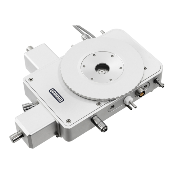
Page 7: Stage Anatomy
Stage Anatomy Stage Assembly 1. Stage body water connector 2. XY Motor cables 3. Gas purge valve 4. Liquid nitrogen cooling connector 5. Manual X-Manipulator thumbscrew 6. X– manipulator motor 7. Y-manipulator motor 8. Manual Y-Manipulator thumbscrew 9. Stage body 10. -
Page 8: Mounting Stage To Microscope With Dovetail Substage
Mounting Stage to Microscope with Dovetail Substage 9541 curved clamps set The following description is for mounting the stage on to microscopes which have a circular dovetail substage assembly (1). Attach the curved stage clamps (part no. 9541) to the base of the stage using the supplied hex screws and the outer most holes in the base plate. -
Page 9: Vacuum Tweezers
Vacuum Tweezers The vacuum tweezers are used to manipulate the sample windows onto the silver block to prevent fingerprints on the glass and scratching the sur- face of the silver block when using standard fine tip metal tweezers. The System is supplied with a Vacuum Tweezers Kit which consists of a Vacuum Pump (1) and tweezers (2). -
Page 10: Connecting The Instruments
Connecting the Instruments T95 System Controller Cable Connections For more details on the T95 System Controller please refer to the T95 System Controller manual. T95 back panel Connect the Stage Cable to the Lemo Connector on the stage and connect the other end to the Stage Connection Socket (1). -
Page 11: Lnp95 Cooling Pump Connection
LNP95 Cooling Pump Connection Remove Transit Screws Before using the LNP95 Liquid Nitrogen Pump System, remove the 4 transit screws, marked by small yellow labels, from the base of the LNP95. Transit screws shown by arrows in the adjacent image. These screws hold the pumps in place for shipping. -
Page 12: Setting Up Ecp Water Circulator Pump
Water Circulator Pump If you have purchased the ECP with the system, read the following to set up the ECP with the MDS600 stage. Refer to the ECP manual for more details. When heating the stage above 300°C for a pro-... -
Page 13: Sample Preparation
The MDS/CC sample holder (1) is used to load larger volume liquid samples using the Quartz Crucible. The MDS/CC is fitted on to the MDS600 stage and hovers a few millimetres above the silver heating block. Place the quartz crucible (2) into the MDS/CC sample holder by placing the crucible into the aperture at the end of the holder. -
Page 14: Mds/Cc Crucible Carrier And Stainless Steel Ring
Pipette the sample into the Quartz Crucible. Use as little sample as possible to ensure a small ther- mal load and therefore better temperature sensi- tivity. Place a W13G (13 x 0.17mm) (1) glass cover slip on top to flatten the sample. Microscope objectives require a flat surface to give maximum field of view. - Page 15 Use the vacuum tweezers or a pair of tweezers as shown and place a W16G (16 x 0.17mm) (1) glass cover slip (1) into the stainless steel ring. Tap the edges lightly to ensure that it sits flat against the surface of the block. If the cover slip does not sit perfectly flat against the temperature controlled surface the heat flow will be compro- mised and the sample temperature will be signifi-...
-
Page 16: Cooling Connections
Cooling Connections These connections need only be made if the experiments are to be carried out below room temperature. The Dewar siphon (1) is the thick white foam tubing and is attached to the liquid nitrogen Dew- ar. The thin black capillary tube inside the white foam tube must be inserted into the liquid nitro- gen cooling connectors on the stage. -
Page 17: Purging Procedure
Purging Procedure Before starting a cooling experiment, you will need to purge air from the stage chamber with dry nitro- gen . This will remove the water in the air which would otherwise condense and freeze on the sample disrupting your image quality. Before you can start purging, the LNP95 must be set to manual mode. -
Page 18: Purging The Stage Method 1
Purging the Stage Method 1 There are two methods for purging the stage. Method 1 uses recycled nitrogen gas produced by the LNP95 from the 2L Dewar. Make sure the stage lid is in place and the stage door is closed. Switch on the temperature programmer and set the limit to 40°C. -
Page 19: Purging The Stage Method 2
Purging the Stage Method 2 This method uses an inert gas from a gas cylinder to purge the stage at temperatures above ambient when the LNP95 is not required. 1. Make sure the Stage Lid is in place and the Stage Door is closed. -
Page 20: Using Linksys32 Software With Mds600 Stage
Using Linksys32 Software with MDS600 Stage Please refer to Linksys32 manual to control the temperature of the MDS600. With Linksys32-DV/AV for digital video/analogue video capture. The following chapter will provide extra information to control the motorised XY manipulators using Linksys32 software and automatically map a sample using Linksys32- DV/AV software with a camera. -
Page 21: Mds Setup Menu
Note: The last two buttons labelled ‘Diagonal’ and ‘Square’ are for testing purposes only. DO NOT USE. Focus (Z) This option is not implemented with the MDS600 Stage, DO NOT USE. Sample area There are a number of different sample holders for the different versions of the motorised stage. -
Page 22: Using Linkpad With Mds600 Stage
With Linksys32 connected and running, the Link- Pad become an active screen and displays infor- mation from Linksys32 Software. With the MDS600 connected the main screen of the LinkPad will display the live position of the X (1) and Y (2) values in µm. -
Page 23: Appendix
Appendix Replacing MDS/CC Crucible Carrier Please read the following chapter to replace the MDS/CC Crucible Carrier. To replace the MDS/CC in the Stage, use a M3 hex key to remove the 6 screws on top of the Stage as indicated by the arrows in the picture opposite. - Page 24 Use a cross head screw driver to remove the 3 screws, indicated by the 3 arrows in the opposite picture and remove the old MDS/CC Sample Holder Do the reverse to install the new MDS/CC Sam- ple Holder. Make sure the new MDS/CC Crucible holder hovers a few millimetres above the silver heating block...
-
Page 25: G10Mt Sample Holder And Sample Mapping
G10MT Sample Holder and Sample Mapping Sample mapping is only possible if you have Linksys32-AV or DV (analogue video or digital video) software and use the Sample Mapping Kit: G10MT (10mm diameter tapered sample holder) W10Q (10 x 0.3mm quartz Sample Window) W9G (9 x 0.17mm glass sample window) The G10MT Sample Holder (1) has a tapered internal edge (2) to enable the straight edge of the... -
Page 26: Sample Preparation Using G10Mt Sample Holder
Sample Preparation Using G10MT Sample Holder Place a W10Q quartz sample window (1) using the vacuum tweezers onto the surface of the silver block next to the end of the sample holder. With one hand carefully lift the G10MT about 1mm off the silver heating block and slide the W10Q sample window directly underneath the circular sample holder. -
Page 27: Sample Mapping Using Linksys32 Software
Sample Mapping Using Linksys32 Software Please refer to the Linksys32 manual for an over- view of the video capture software and how to capture images and setup your camera. The mapping feature enables the video capture software to build up a mosaic map of the sample by capturing images as the sample holder is moved through viewing area. - Page 28 When the Capture Module Record Button (1) has been pressed, a map setup window will ask you to setup the area of the sample to be mapped. Follow the on screen instructions to set the start and end position of the sample to be mapped. Start Position Use the MDS Module joystick control to set the start of the scan area.
- Page 29 The image below shows a map being created for a fluid inclusion sample. The small image shows what is seen by the microscope and the larger image shows the entire sample in the process of being mapped.
-
Page 30: Window Assembly
Window Assembly Lid Window Assembly To replace the windows in the Stage Lid (1) use the Window Tool (2) and align the two wide spacing pins to the Tube Clip Holder holes and unscrew the Lid Insert (3). The Stage Lid and Lid Insert should be turned upside down as shown in the diagram opposite and reassembled in the order indicated. -
Page 31: Spares And Accessories
Spares and Acessories These spares are organised into convenient kits. Purchase a spares kit to avoid downtime with your stage and eliminate future shipping costs. Part No. Part Name Part Description 22222 MDS Kit Full Replacement Spares Kit Water/Gas Valve Insert x2 Water/Gas Valve Connector x2 Silicon Rings for Lid and Base (Set of 4) Tube Clip Holder (for Nitrogen de-fogging stage lid tube) - Page 32 Part Part Name Part Description 22222 G10MT Kit G10MT Sample Mapping Kit G10MT 10mm Sample Holder (tapered) W10Q 10mm diameter Quartz Sample Window (0.3mm thick) x2 9mm diameter Glass Sample Window (0.17mm thick) Box of 100...
-
Page 33: Troubleshooting
Troubleshooting Cooling fault diagnosis Ensure that all connections to the stage and Dewar are as described in the specific manual and that the stage lid and top windows are properly sealed. 1. The cooling rate is less than programmed. There can be several causes of this problem, the most likely being that one of the connectors has become blocked or damaged. - Page 34 This page is intentionally blank...
- Page 35 This page is intentionally blank...
-
Page 36: Contact Details
Linkam Scientific Instruments Ltd Tel: +44(0)1737 363 476 Fax: +44(0)1737 363 480 Email: support@linkam.co.uk Unit 8 Epsom Downs Metro Centre Waterfield, Tadworth, Surrey, KT20 5LR, UK www.linkam.co.uk Version: 1.03.0210...
Need help?
Do you have a question about the MDS600 and is the answer not in the manual?
Questions and answers