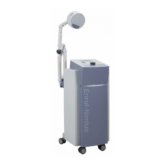
Enraf Nonius Curapuls 670 Service Manual
Hide thumbs
Also See for Curapuls 670:
- Operating instructions manual (69 pages) ,
- Information sheet (2 pages) ,
- Manual (204 pages)
Table of Contents
Advertisement
Advertisement
Table of Contents

Related Manuals for Enraf Nonius Curapuls 670


Summary of Contents for Enraf Nonius Curapuls 670
- Page 1 Curapuls 670 SERVICE MANUAL Part number: 1403773...
- Page 3 Enraf-Nonius B.V. Curapuls 670 Service Manual 1403773 Curapuls 670 SERVICE MANUAL Copyright: Enraf-Nonius B.V. P.O.Box 810 2600 AV Delft The Netherlands part number: 1403.773-40 PDF master 01042001 Index June 1997...
-
Page 4: Table Of Contents
Enraf-Nonius B.V. Curapuls 670 Service Manual 1403773 CONTENTS Date of issue page INTRODUCTION ........ - Page 5 Jun. 1997 B-1 Fig. 2 Curapuls 670 top view ......Jun. 1997 B-2 Fig. 3 Curapuls 670 front view .
- Page 6 Enraf-Nonius B.V. Curapuls 670 Service Manual 1403773 Index June 1997...
-
Page 7: Introduction
INTRODUCTORY REMARKS This manual has been written for the technicians involved in the service of the Curapuls 670. Service can be carried out by the service organization of the supplier or by any other technician authorized by Enraf-Nonius B.V. The manufacturer will not be held responsible for the results of maintenance or repairs by unauthorized persons. - Page 8 Such are for example parts as transformers, PC Boards, key-boards and software. The registered parts of the Curapuls 670 are marked with a "Y" for "Yes" in the spare parts list in appendix A (column C).
- Page 9 Enraf-Nonius B.V. Curapuls 670 Service Manual 1403773 1.1.5 Product documentation The documentation set for the Curapuls 670 also incudes an Instruction manual and therapy books. The instruction manual is a recommended item for all service engineers. Ordering data: - 1403.751 Instruction manual - 1403.773...
-
Page 10: General
Curapuls 670 for safety and correct functioning. The Curapuls 670 menu can be set in five languages, GB, NL, D, F, E. Changing languages can be done by pressing the “cursor left” key for approx. 2 sec. in the main menu. -
Page 11: Technical Data
Continuous microprocessor-controlled fine tuning ensures optimum adaptation to the tissue characteristics. Special high-output inductive electrodes have been developed for use with the Curapuls 670. These are of the ’Circuplode’ type, and are available in small, large and elliptic treatment areas. They are provided with screening for the electrical field so that only a magnetic field* is created. - Page 12 I: The equipment has a safety earth (ground) connection, and must be connected to a wall socket with protective earth connection. BF: The equipment has a floating patient circuit. The Curapuls 670 meets the requirements of IEC 601 series safety standards.
-
Page 13: Description
EPROM. Timer circuits are used for generating treatment parameters and for measuring the output signals. Safety circuits are applied for checking the safe operation of the Curapuls 670, also is checked that the output does not exceed maximum values. All signals are generated by the P and converted by a DA converter to analogue signals. - Page 14 2.1.3 Mains supply circuit The mains power is fed into the Curapuls 670 via a mains entrance. Inside the mains entrance two mains fuses are found. The mains power runs via a mains filter and a mains switch to the primary side of the mains transformer. The mains power is transformed into 12V, 18.5V, 18.5V, 24V and 160V and fed into the power supply...
-
Page 15: Test Equipment And Tools
TEST EQUIPMENT AND TOOLS TEST EQUIPMENT For the repair and maintenance procedures of the Curapuls 670 the following test equipment and accessories are required: - Digital multimeter 3 1/2 digit, accuracy better than 1 %. (2x) For example Fluke 77 - Two beam oscilloscope, >30MHz, accuracy better than 5%. - Page 16 Enraf-Nonius B.V. Curapuls 670 Service Manual 1403773 Test equipment and tools June 1997...
-
Page 17: Maintenance
Connect the Curapuls 670 to the mains and switch on the equipment. The Curapuls 670 will carry out the so-called self test for approx. 10 seconds. At the end the buzzer sounds (otherwise see par. 4.4.1.2 - 4 ). It is assumed that when the selftest is passed all functions of the Curapuls 670 are okay. - Page 18 (otherwise see par. 4.4.1.7). Entering the service mode: Testing of other parts of the Curapuls 670 is done in the so called “SERVICE MODE”. For starting the service mode enter the following key code when in control panel test mode, press in sequential order the following keys:...
- Page 19 Enraf-Nonius B.V. Curapuls 670 Service Manual 1403773 Continue with the next test or leave the service mode by switching off the Curapuls 670. 4.3.5 Display test Enter the service mode and select test 50 To enter the display test press the start/stop key.
- Page 20 Stop the identification test by pressing the start/stop key. Continue with the next test or leave the service mode by switching off the Curapuls 670. 4.3.9 Safety relay test Enter the service mode and select test 11 This test controls the safety relay and switches it on and off with a frequency of 1 Hz.
- Page 21 FUNCTIONAL TESTS IN OPERATING MODE: The next tests are done in operating mode. To end the service mode switch off the Curapuls 670. Switch on the Curapuls 670 and wait until the selftest is ended. Select Treatment parameters in the MAIN MENU.
-
Page 22: Trouble Shooting
4.4.1.9). 4.3.16 Output power Check the power using the Curapuls 670 power meter and 50 ohms dummy in combination with a voltmeter. Connect the power meter and dummy to channel A. Connect the voltmeter to the banana type plugs. - Page 23 These error codes can be generated when starting up (during selftest) or during operation. An error message is indicated by an audio signal and an error code on the LCD display of the Curapuls 670. 4.4.3 Error code list Error code numbers which can be generated are form 0 up to 67.
-
Page 24: Replacement Procedures
REPLACEMENT PROCEDURES 4.5.1 General When handling static sensitive devices such as the PC Boards of the Curapuls 670 the following precautions should be observed: - Persons should be earthed by means of a wrist strap - Ground all electrical equipment, work-bench, soldering iron etc. - Page 25 Enraf-Nonius B.V. Curapuls 670 Service Manual 1403773 Installation: Installation of the front cover is in reverse order of the removal procedure. 4.5.3 Top cover Removal: Remove the front cover (see par. 4.5.2). Remove the four screws at the top at the inside of the housing. Disconnect the cables from CN1 and CN2 from the main PC Board.
-
Page 26: Adjustment Procedures
For wiring of the mains transformer see appendix B, fig. 9. ADJUSTMENT PROCEDURES The adjustment procedure for the Curapuls 670 is carried out under the following test conditions: - The mains voltage must correspond with the technical specifications of the Curapuls 670 - The ambient temperature must be 25°... - Page 27 - voltmeter (multimeter) Note: After a repair or adjustment of the main PC Board a burn-in test is recommended for testing of the proper functioning of the Curapuls 670. 4.6.3 Adjustment Voltage Controlled Oscillator (test 37) - Select test 37, par. 4.6.3 (see par. 4.3.2 for entering the service mode).
- Page 28 6 Volt, if not, replace the battery. Power adjustment output stage - Switch off the Curapuls 670. - Connect the Curapuls 670 power meter to channel A with a coax cable 50 length 1.50 m. - Connect the 50 dummy to the power meter with a coax cable 50 length 0.60 m..
- Page 29 400V. are present. Do not touch when the Curapuls 670 is switched on! - Switch on the Curapuls 670 and select test 38, par. 4.6.4. (see par. 4.3.2 for entering the service mode). - Choose subselection 0 (300W HF output) and press the start / stop key, C162 Adjust C162 until the voltmeter gives a maximum reading.
- Page 30 Enraf-Nonius B.V. Curapuls 670 Service Manual 1403773 Maintenance 4-14 June 1997...
-
Page 31: Storage And Transport
STORAGE The Curapuls 670 and any accessories must always be stored in their original packing. The long term storage conditions are: - The unit must be stored at room temperature (± 20 °C). - Page 32 Enraf-Nonius B.V. Curapuls 670 Service Manual 1403773 Storage and transport June 1997...
-
Page 33: Spare Parts
Enraf-Nonius B.V. Curapuls 670 Service Manual 1403773 SPARE PARTS This chapter deals with placing orders for spare parts (refer to appendix A) as well as the listing of the actual spare parts (appendix A, spare parts list). ORDERING Spare parts can only be ordered if the following data is supplied:... -
Page 34: Repair Service
Enraf-Nonius B.V. Curapuls 670 Service Manual 1403773 REPAIR SERVICE Defective PC Boards can be offered to Enraf-Nonius for repair. The repair order can be presented to Enraf-Nonius by means of the "Authorization Request for Return Shipment". Refer to the return shipment procedure as per par. 6.4. - Page 35 Enraf-Nonius B.V. Curapuls 670 Service Manual 1403773 APPENDIX A SPARE PARTS LIST The spare parts list on the next page shows all available spare parts. The various columns are explained hereafter: Item: The item number refers to the number on the illustration(s).
-
Page 36: Appendix A Spare Parts List
Enraf-Nonius B.V. Curapuls 670 Service Manual 1403773 Spare parts list Item Part no. Description1 Description2 2994804 Knob 2994806 Spacer, felt, for knob (item 001) 44x3mm 2188076 Castor 2188077 Castor, with brake 2570037 Cable, Coax, BNC-BNC, internal, HF. output 0403801 Test equipment, Dummy load 50... -
Page 37: Appendix B Drawings
Enraf-Nonius B.V. Curapuls 670 Service Manual 1403773 APPENDIX B DRAWINGS Figure 1 Block diagram Appendix B June 1997... -
Page 38: Curapuls 670 Top View
Enraf-Nonius B.V. Curapuls 670 Service Manual 1403773 Figure 2 Curapuls 670 top view Appendix B June 1997... -
Page 39: Curapuls 670 Front View
Enraf-Nonius B.V. Curapuls 670 Service Manual 1403773 Figure 3 Curapuls 670 front view Appendix B June 1997... - Page 40 Enraf-Nonius B.V. Curapuls 670 Service Manual 1403773 Figure 4a Chassis front view, top cover Figure 4b Chassis front view, chassis Appendix B June 1997...
-
Page 41: Main Pc Board, Pcb Id: 2558.568
Enraf-Nonius B.V. Curapuls 670 Service Manual 1403773 Figure 5 Main PC Board, PCB id: 2558.568 Appendix B June 1997... - Page 42 Software 0403703 ID A3 version 03 in EPROM (HF.) for use with Curapuls 403 0403704 ID A4 version 04 in EPROM (HF.) for use with Curapuls 670 Service Circuit adjustments: L3 (frequency), C162, L20, L23, P1 (output stage) Serviceable parts for FSE:...
-
Page 43: User Interface Pc Board, Pcb Id: 2558.863
Enraf-Nonius B.V. Curapuls 670 Service Manual 1403773 Figure 6 User interface PC Board, PCB id: 2558.863 Appendix B June 1997... - Page 44 EPROM (IC2) Repairable by manufacturer: Yes Application / compatibility User Interface PC Board used for Curapuls 670 units with back light LCD display. Note: The PC Board will be supplied without software, use the software (EPROM IC2) which is used on the PC Board which is to be replaced.
-
Page 45: Curapuls 670 Power Supply Check
Enraf-Nonius B.V. Curapuls 670 Service Manual 1403773 Figure 7 Curapuls 670 power supply check. Appendix B June 1997... -
Page 46: Curapuls 670 Adjustment
Enraf-Nonius B.V. Curapuls 670 Service Manual 1403773 Figure 8 Curapuls 670 adjustment. Appendix B B-10 June 1997... - Page 47 Enraf-Nonius B.V. Curapuls 670 Service Manual 1403773 Figure 9 115/220-240 VAC Mains power supply configuration Appendix B B-11 June 1997...
- Page 48 Enraf-Nonius B.V. Curapuls 670 Service Manual 1403773 Appendix B B-12 June 1997...
-
Page 49: Appendix C Service Info's (Product Change Notes)
Enraf-Nonius B.V. Curapuls 670 Service Manual 1403773 APPENDIX C SERVICE INFO’S (Product Change Notes) GENERAL The technical information in the service manuals of Enraf-Nonius is up to date from the date of issue. The necessary additional information (of any kind) will be provided in the following way:... -
Page 50: Revision History
Enraf-Nonius B.V. Curapuls 670 Service Manual 1403773 Revision history First edition: June 1997 Revisions: Chapter: Revision: Date of issue: page Appendix C June 1997... - Page 51 To modify the function of the arm the three joints with a knob must be altered. • Remove the arm from the equipment (for the Curapuls 670): do not remove both arms at the same time; otherwise it might not be possible to remount the arms) •...
- Page 52 Perform only upon unit failure. Information only Commencing date: October 31, 1997 Carried out from series: Curapuls 670 - 01001; Curapuls 970 - 01001 New components: 0431.804 (service set) Deleted components: three knobs, two spider springs, two M10 rings, manual 0169.285-41...
- Page 53 Service Information Curapuls 670, changes main PC Board. The heatsink at the bottom side of the main PC Board of the Curapuls 670 has been changed. The PC Board will be shipped completely mounted and wired. Because of the changes, the replacement of the main PC Board is changed.
- Page 54 Please add this service info to appendix C of your service manual. Change classification Perform immediately on all field units. Perform routinely at next service call. Perform only upon unit failure. Information only Commencing date: July 1998 Carried out from series: 11.000 New components: Deleted components:...
- Page 55 The Netherlands Service Information Curapuls 670, Preventive spraying of the main PC Board To prevent high voltage break-down due to slowly increasing the mains voltage from 220VAC -> 230VAC last years, it is recommended to put an insulation lacquer on the rear (solder) side of the main PC Board.
- Page 57 This service information sheet describes how to improve the thermal contact of the main PC Board heatsink to the chassis of the Curapuls 670. The new type main PC Board (see also service information sheet SI 670 - 02) is equipped with an heatsink which is directly mounted to the chassis of the unit.
- Page 58 Figure 1 Detail of the main PC Board No: SI 670 - 02 Page 2 of 2 Oct. 1998...
- Page 60 Subsidiary of Henley Healthcare Inc. Enraf-Nonius B.V. P.O. Box 810 2600 AV Delft The Netherlands...
Need help?
Do you have a question about the Curapuls 670 and is the answer not in the manual?
Questions and answers
Does this curplus 670 affect other organs like kidney and liver and hiw ?