
Subscribe to Our Youtube Channel
Related Manuals for Ger Detect EASY WAY SMART


Summary of Contents for Ger Detect EASY WAY SMART
- Page 2 INDEX Section 1 Critical Warning Section 2 Overview Section 3 Definition of the main unit buttons Section 4 The long-range system Section 5 Long-range system parts connection Section 6 Long -range system operation steps Section 7 The 3D imaging system Section 8 3D imaging system communication steps Section 9...
- Page 3 Section 1 (Critical warning) - Please be sure that all precautions are taken against risks. - Do not use your device while it is raining or on extremely wet floor. - Turn on the device after you make sure that all parts are in place and connected. - Make sure that the device battery is fully charged before you start the search.
-
Page 4: Section 2 (Overview)
✓ Specialized in prospecting and searching for gold, precious metals, burials, caves and voids inside the ground, with confidentiality and ease. ✓ EASY WAY SMART is designed to operate in all kinds of terrain and in the most difficult climatic conditions. - Page 5 Section 3 (Definition of the main unit buttons) Description Power Indicator: which lights up when the device is turned on after long pressing the power button. Power button: turn on the device by pressing the power button for two seconds. Long-range System Indicator: which lights up when activating the long- range radar system.
- Page 6 Section 4 (The long-range system) Transmitter and receiver antenna Part 1 Transmitter and receiver antenna Part 2 Radar system grip The main unit Signal transmission cable...
- Page 7 Section 5 (Long-range system parts connection) Step (1) Step (2) Step (3) Step (4)
- Page 8 Section 6 (Long -range system operation steps) (1) Connect the two parts of the antenna together. (2) Install the sensor handle to the antenna. (3) Connect the signal transmission cable between the sensor system handle on the one side and (4) the main unit on the other side. As a user, you should remove all holdings that may affect the functionality of the device such as a wrist watch, mobile phone, wallet, ring, and belt.
- Page 9 The long-range system will operate automatically with its light indicator on. You can choose the target type by pressing the Up and Down buttons. After selecting the target to be searched for, securely place the main unit to your waist and then hold the sensor grip at a 90-degree angle in order for the antenna to function properly.
- Page 10 If no signal is obtained, change your direction from east to west, from west to east, and from south to north. When a signal is sensed, the antenna will turn towards the target directly. Follow the signal until the antenna turns back, this means that you have walked past the target.
- Page 11 Section 7 (The 3D imaging system) (1) Unplug the signal cable from the main unit (2) Select the 3D imaging system by pressing the 3D button with the imaging system and Bluetooth lights on.
- Page 12 Section 8 (3D imaging system communication steps) connect the main unit to the tablet device via Bluetooth, by pressing and holding on the Bluetooth icon GER3D...
- Page 13 Bluetooth will search for devices near your tablet. Then the Bluetooth will appear like GER3D GER3D GER3D Click on the device name, a window will appear to enter the password which is: 1000 GER3D?
- Page 14 Press OK to complete the pairing operation between the tablet and the main unit. Close the window and run GER 3D Viewer program...
- Page 15 Section 9 (GER 3D VIEWER operation steps) A list of several languages will appear: (German, English, French, Italian, Spanish, Arabic, Portuguese, and Russian). Select the device you want to work on “Easy way”...
- Page 16 The program will connect to the device Then a CONNECTED sign will then appear...
- Page 17 Press the Next button to go to Scan settings menu, which consists of: Scanning Direction - Number of lines - Number of Steps...
- Page 18 Scanning Direction: is to select the scanning method during imaging And there are two methods for scanning Either scan in one direction Or two-way scanning, back and forth. Number of lines: to determine the number of lines within to search. Number of Steps: for each line to determine the images within one line.
- Page 19 Section 10 (3D imaging system operation steps) Then press Next to open the software interface Walk in consecutive steps at a distance of 30 cm between every two steps taking into account keeping a 30-cm distance from the first line while scanning backwards.
- Page 20 During the scanning process, a 3D image of the target being imaged will appear on the tablet screen. This image consists of a grid of squares indicating the number of steps and lines that have been scanned . Example: We have a grid of lines consisting of three columns and ten steps per column, which means three lines of scan, and each line consists of ten images captured.
- Page 21 To view the depth, press the View Depth icon. To reduce image height, use the drop and height icon of the image in the blue color. The two red icons are used to make the image clearer and reduce the mineral salts surrounding the minerals and cavities as well as bring the image closer to...
- Page 22 3D icon: it enables you to shift form the 2D to the 3D mode To open an image previously saved, click on the Open icon and then press the in the phots itself. To save the image in a format that can be analyzed later, click on the save icon...
- Page 23 To save the image in a PNG format, click on Save PNG icon To reset the image to default, click on the Reset icon To hide and/or show gridlines, click on the Grid icon To zoom in or out, touch and drag the photo...
- Page 24 Moving to the image captured, it is divided into four colors as follows: color: for metals Yellow color: for mineral salts Green color: for soil Blue color: for cavity light blue color: for the rocks surrounding voids You can change colors from the settings where you will find several ready styles Note: changing colors does not...
- Page 25 The values in every image are interpreted as follows: All squares of red color will have close values with slight differences. If two squares have values by a large difference (i.e. 20 to 30 points), this indicates that one of these squares is metal and the other is mineral salts with high concentration.
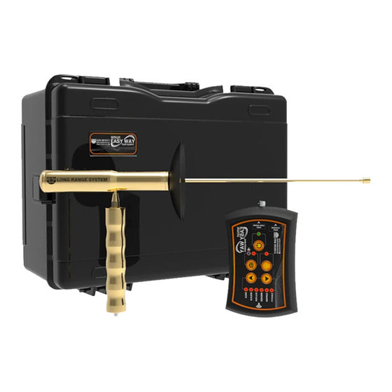
- Page 26 A shock-resistant protective bag made of plastic to carry the device. The main unit Radar system grip Transmitter and receiver antenna Two years guarantee...
- Page 27 A TABLET PC The device charger The car charger Signal transmission cable. The device case for the bottom of the leg We wish you the best of luck Thanks for choosing searching our products in your...
Need help?
Do you have a question about the EASY WAY SMART and is the answer not in the manual?
Questions and answers