Advertisement
Quick Links
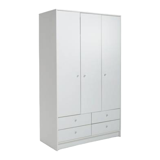
4 DRAWER 3 DOOR ROBE MK2
MADE IN
BRITAIN
Recycling – the packaging materials for this product may be recycled
through your local recycling centre. When you want to dispose of the
product itself, please consider donating it to a local charitable
organisation, otherwise recycle it through your local recycling centre.
MALIBU
PRODUCT CODE : ZMB43R2
Do you need help?
Tip: To prevent damage, we
recommend that you build
your unit on the carton(s) it
If you have any problems
please phone us on
08456 400 800
was packed in.
A
92506
Advertisement

Related Manuals for Malibu Boats ZMB43R2


Summary of Contents for Malibu Boats ZMB43R2
- Page 1 MALIBU 4 DRAWER 3 DOOR ROBE MK2 PRODUCT CODE : ZMB43R2 Tip: To prevent damage, we recommend that you build your unit on the carton(s) it was packed in. Do you need help? If you have any problems please phone us on...
- Page 2 F65 x 1 F197 x 23 F901 x 8 F50 x 7 F461 x 2 F432 x 2 F327 x 1 F79 x 9 F63 x 14 F51 x 33 F110 x 12 F3 x 8 F22 x 18 ZMB43R2 92506...
- Page 3 531 x 157mm Packed in Box 1 Packed in Box 1 Tip: When you insert F3, make sure the ‘arrow’ is pointing towards hole in edge of Wrap. Drawer Wrap - W233 1121 x 95mm Packed in Box 1 ZMB43R2 92506...
- Page 4 - more than 1/2 a turn. Important: Carefully break off the 2 Drawer Stops (F599) from each pair of the Runners. Push the Drawer Stops fully through the Wraps from the inside. ‘SNAP!’ ‘SNAP!’ F599 x 2 F599 ZMB43R2 92506...
- Page 5 F631 F1014 F523 Left Side - D0145A 1808 x 496mm Packed in Box 2 F523 F600 F600 x 2 F523 F523 Right Side - D0146A 1808 x 496mm F601 x 2 Packed in Box 2 F601 ZMB43R2 92506...
- Page 6 Top - D0149A 1069 x 494mm Packed in Box 2 F365 F197 x 2 Top - D0149A Right Side - D0146A Covered Edge F1014 Upright - D0147A 1356 x 477mm Packed in Box 1 F523 F523 ZMB43R2 92506...
- Page 7 Lower Shelf - D0151A Horizontal - D0150A 1069 x 478mm 714 x 446mm Packed in Box 2 Packed in Box 2 F197 x 2 F197 x 2 F365 Covered Horizontal - D0150A Edge F197 x 2 Lower Shelf - D0151A ZMB43R2 92506...
- Page 8 Over Divider - D0148A 314 x 477mm F601 x 2 Packed in Box 2 Covered Edge F601 Tip: This panel has 2 holes drilled in the middle. Back Rail - D0154A 1069 x 92mm Packed in Box 2 ZMB43R2 92506...
- Page 9 F365 F197 x 2 F197 Divider - D0148A Back Rail - D0154A Plinth - D0153A 1069 x 92mm Packed in Box 2 F22 x 2 Rail - D0155A 1069 x 92mm Packed in Box 2 F22 x 2 ZMB43R2 92506...
- Page 10 F197 F365 Rail - D0155A Plinth - D0153A Covered Edge F197 x 4 Left Side - D0145A F197 x 4 F365 ZMB43R2 92506...
- Page 11 Nails should be about 150mm apart. Using 8 x F79, screw down between the Backs and into the edge of the Upright panel. F79 x 8 F149 Back - X710 1380 x 358mm Foldy Back - X711 1380 x 732mm STAND UNIT ZMB43R2 92506...
- Page 12 Furniture Polish into the grooves Lift front of Drawer whilst inserting to overcome the 'stop' system. Loose Shelf - D0152A 340 x 446mm 1 Packed in Box 2 F110 x 4 2 Packed in Box 1 F110 x 4 F110 x 4 ZMB43R2 92506...
- Page 13 DO NOT ONLY drill drill this this hole hole Door - D0156A in ONE of the Doors Door - D0156A ONLY drill this hole in TWO of the Doors DO NOT drill this hole ZMB43R2 92506...
- Page 14 Tip: Using 2 people, fit the holes must be near the top Hinge first, then align bottom of the Doors and fit the other Hinge. F631 Important: When securing the handles please ensure you do not over tighten the screws. ZMB43R2 92506...
- Page 15 Drill through the 2 circled holes into the next Side panel. Push the connectors F432 x 2 into the 2 holes (circled) and then screw bolts F461 in from the other side. Tighten with a screwdriver. F461 F432 ZMB43R2 92506...
- Page 16 Now all you have to do is fill it with all your bits and pieces! Take care of your unit by using a damp cloth to clean it. Please remember to occasionally check that all Cams and Screws are tight. ZMB43R2 92506...
- Page 17 Malibu - 4 Drawer 3 Door Robe Assembly Instructions - 643/6520 Please keep for future reference 643/6506 643/6537 643/6489 643/8542 Dimensions Width - 110cm Depth - 50cm MADE IN Height - 181cm BRITAIN Important - Please read these instructions fully before starting assembly If you need help or have damaged or missing parts, call the Customer Helpline: 08456 400800 Issue 1 - 21/01/10...
- Page 18 Safety and Care Advice Important - Please read these instructions fully before starting assembly • Warning: This unit weighs • Make sure you have enough • We do not approximately 79kgs. Please lift space to layout the parts before recommend the with care.
- Page 19 If you have damaged or missing components, call the Components - Panels Customer Helpline: 08456 400800 quoting the reference numbers below Please check you have all the panels listed below Horizontal (D0150A) (714 x 446mm) Divider (D0148A) (314 x 477mm) Upright (D0147A) (1356 x 477mm)
- Page 20 If you have damaged or missing components, call the Components - Fittings Customer Helpline: 08456 400800 quoting the reference numbers below Please check you have all the fittings listed below Note: The quantities below are the correct amount to complete the assembly. In some cases more fittings may be supplied than are required.
- Page 21 If you have damaged or missing components, call the Assembly Instructions Customer Helpline: 08456 400800 quoting the reference numbers below Step 1 Prepare 4 drawer fronts and wraps Note: The right drawer front has a small Identification identification hole. hole Screw 2 metal dowels into the holes...
- Page 22 Assembly Instructions Step 3 Fit the drawer stops Carefully break off the 2 drawer stops (F599) from each pair of the drawer runners Push the drawer stops fully through the drawer wraps from the inside. F599 F599 F599 F599 Step 4 Attach the handles Attach a handle each drawer front...
- Page 23 Assembly Instructions Step 5 Prepare the left and right side F600 Separate runners Push fit 2 left runners marked ‘L’ into the holes shown on left side Finished front edge Note: Runners must be be fitted flat against the panel. If necessary gently tap into final position.
- Page 24 Assembly Instructions Step 6 Prepare the top Tap 2 wooden dowels into the ends of the Step 7 Fit the top to the right side Attach the top to the right side using the dowel already fitted and secure with 2 screws Finished front edge Finished...
- Page 25 Assembly Instructions Step 9 Fit the upright to the Attach the upright the top using the dowel already fitted and secure with 2 screws Finished front edge Step 10 Plain chipboard surface Prepare the lower shelf Tap 2 wooden dowels into the ends of the lower shelf Step 11...
- Page 26 Assembly Instructions Assembly Instructions Step 12 Prepare the horizontal Tap 2 wooden dowels into the ends of the horizontal Step 13 Fit the horizontal to the upright Attach the horizontal to the upright using the dowel already fitted and secure with 2 screws Finished front edge...
- Page 27 Assembly Instructions Step 14 Finished Prepare both surfaces front edge of the divider F600 Push fit 2 left runners marked ‘L’ into the divider Tap in 2 wooden dowels , as shown. Turn the divider over Turn divider over Push fit 2 right runners marked ‘R’...
- Page 28 Assembly Instructions Step 16 Plain Prepare the back rail, chipboard rail and plinth 2 holes surface Tap 2 wooden dowels into the ends of the back rail Tap 4 wooden dowels into the ends of the Plain rail chipboard 1 hole surface Tap 2 wooden dowels into the ends of the...
- Page 29 Assembly Instructions Step 18 Fit the rail and plinth Attach the rail to the right side using the dowels already fitted. Attach the plinth to the right side and and secure with screw Finished front edge Step 19 Fit the left side and secure the rail to the divider Attach the left side...
- Page 30 Assembly Instructions Step 20 The measurement from top corner X to bottom corner X must be equal to the measurement from top corner Y to bottom corner Y Fit the back panel Square up the unit by making sure that measurement x to x equals y to y.
- Page 31 Assembly Instructions Step 21 Fit the hanging rail and drawers Push the hanging rail into the rail holders on the side panels. Lift the front of the drawer whilst inserting to overcome the ‘stop’ system. Note: Remember the right drawer front has an identification hole - refer back to step 1.
- Page 32 Assembly Instructions Step 23 Prepare the 3 doors Push fit the hinges into the door Secure each hinge with 2 screws Note: Before securing with the screws, make sure that the hinges are positioned at 90 degrees with the front edge of the door.
- Page 33 Assembly Instructions Step 25 Fit doors and handles screw A 2 people are needed here Note: The easiest way to attach the doors is to fit the top hinge first, then align and fit the bottom hinge. screw B Push the hinge onto the front part of the hinge plate Keep the hinge...
- Page 34 Assembly Instructions Step 26 Adjust the doors if required Before adjusting the doors, use a spirit level to check the lower shelf (or top) of the unit is level, front-to-back and side-to-side in the 3 positions shown. Use suitable packing pieces (not supplied) to make the unit level BEFORE making any...
- Page 35 Assembly Instructions Step 27 Joining units together Fittings have been supplied so you are able to join units together. Make sure that your first unit is level. Push the other unit up against the first unit and ensure both units are level.
- Page 36 Assembly Instructions Step Attach bracket to top To prevent possible overbalancing, we recommend that this unit is secured to a suitable wall by use of the bracket fitted to the top of the unit. Fixings are not supplied, as they will need to suit the wall type and the length of screw will depend on the distance...
- Page 37 Malibu - 4 Drawer 3 Door Robe Assembly Instructions - 643/6520 Please keep for future reference 643/6506 643/6537 643/6489 643/8542 Dimensions Width - 110cm Depth - 50cm MADE IN Height - 181cm BRITAIN Important - Please read these instructions fully before starting assembly If you need help or have damaged or missing parts, call the Customer Helpline: 08456 400800 Issue 2 - 17/09/12...
- Page 38 Safety and Care Advice Important - Please read these instructions fully before starting assembly • Warning: This unit weighs • Make sure you have enough • We do not approximately 79kgs. Please lift space to layout the parts before recommend the with care.
- Page 39 If you have damaged or missing components, call the Components - Panels Customer Helpline: 08456 400800 quoting the reference numbers below Please check you have all the panels listed below Horizontal (D0150A) (714 x 446mm) Divider (D0148A) (314 x 477mm) Upright (D0147A) (1356 x 477mm)
- Page 40 If you have damaged or missing components, call the Components - Fittings Customer Helpline: 08456 400800 quoting the reference numbers below Please check you have all the fittings listed below Note: The quantities below are the correct amount to complete the assembly. In some cases more fittings may be supplied than are required.
- Page 41 If you have damaged or missing components, call the Assembly Instructions Customer Helpline: 08456 400800 quoting the reference numbers below Step 1 Prepare 4 drawer fronts and wraps Note: The right drawer front has a small Identification identification hole. hole Screw 2 metal dowels into the holes...
- Page 42 Assembly Instructions Step 3 Fit the drawer stops Carefully break off the 2 drawer stops (F599) from each pair of the drawer runners Push the drawer stops fully through the drawer wraps from the inside. F599 F599 F599 F599 Step 4 Attach the handles Attach a handle each drawer front...
- Page 43 Assembly Instructions Step 5 Prepare the left and right side F600 Separate runners Push fit 2 left runners marked ‘L’ into the holes shown on left side Finished front edge Note: Runners must be be fitted flat against the panel. If necessary gently tap into final position.
- Page 44 Assembly Instructions Step 6 Prepare the top Tap 2 wooden dowels into the ends of the Step 7 Fit the top to the right side Attach the top to the right side using the dowel already fitted and secure with 2 screws Finished front edge Finished...
- Page 45 Assembly Instructions Step 9 Fit the upright to the Attach the upright the top using the dowel already fitted and secure with 2 screws Finished front edge Step 10 Plain chipboard surface Prepare the lower shelf Tap 2 wooden dowels into the ends of the lower shelf Step 11...
- Page 46 Assembly Instructions Assembly Instructions Step 12 Prepare the horizontal Tap 2 wooden dowels into the ends of the horizontal Step 13 Fit the horizontal to the upright Attach the horizontal to the upright using the dowel already fitted and secure with 2 screws Finished front edge...
- Page 47 Assembly Instructions Step 14 Finished Prepare both surfaces front edge of the divider F600 Push fit 2 left runners marked ‘L’ into the divider Tap in 2 wooden dowels , as shown. Turn the divider over Turn divider over Push fit 2 right runners marked ‘R’...
- Page 48 Assembly Instructions Step 16 Plain Prepare the back rail, chipboard rail and plinth 2 holes surface Tap 2 wooden dowels into the ends of the back rail Tap 4 wooden dowels into the ends of the Plain rail chipboard 1 hole surface Tap 2 wooden dowels into the ends of the...
- Page 49 Assembly Instructions Step 18 Fit the rail and plinth Attach the rail to the right side using the dowels already fitted. Attach the plinth to the right side and and secure with screw Finished front edge Step 19 Fit the left side and secure the rail to the divider Attach the left side...
- Page 50 Assembly Instructions Step 20 The measurement from top corner X to bottom corner X must be equal to the measurement from top corner Y to bottom corner Y Fit the back panel Square up the unit by making sure that measurement x to x equals y to y.
- Page 51 Assembly Instructions Step 21 Fit the hanging rail and drawers Push the hanging rail into the rail holders on the side panels. Lift the front of the drawer whilst inserting to overcome the ‘stop’ system. Note: Remember the right drawer front has an identification hole - refer back to step 1.
- Page 52 Assembly Instructions Step 23 Prepare the 3 doors Push fit the hinges into the door Secure each hinge with 2 screws Note: Before securing with the screws, make sure that the hinges are positioned at 90 degrees with the front edge of the door.
- Page 53 Assembly Instructions Step 25 Fit doors and handles screw A 2 people are needed here Note: The easiest way to attach the doors is to fit the top hinge first, then align and fit the bottom hinge. screw B Push the hinge onto the front part of the hinge plate Keep the hinge...
- Page 54 Assembly Instructions Step 26 Adjust the doors if required Before adjusting the doors, use a spirit level to check the lower shelf (or top) of the unit is level, front-to-back and side-to-side in the 3 positions shown. Use suitable packing pieces (not supplied) to make the unit level BEFORE making any...
- Page 55 Assembly Instructions Step 27 Joining units together Fittings have been supplied so you are able to join units together. Make sure that your first unit is level. Push the other unit up against the first unit and ensure both units are level.
- Page 56 Assembly Instructions Step Attach bracket to top To prevent possible overbalancing, we recommend that this unit is secured to a suitable wall by use of the bracket fitted to the top of the unit. Fixings are not supplied, as they will need to suit the wall type and the length of screw will depend on the distance...
Need help?
Do you have a question about the ZMB43R2 and is the answer not in the manual?
Questions and answers