
Related Manuals for AMS AFDAU T-1


Summary of Contents for AMS AFDAU T-1
- Page 1 AFDAU T-1 Aerial Firefighting Data Acquisition Unit Installation Manual AMS-IM-1-01 Rev. 7 22 September 2021...
- Page 2 AMS installer. This warranty covers the cost of all materials and labour to repair or replace the unit but does not include the cost of transporting the defective unit to and from AMS or its designated warranty repair centre, or of removing and replacing the defective unit in the aircraft.
- Page 3 The following information boxes are used to draw the installers attention to specific facts relevant to the information being presented. CAUTION IMPORTANT INFORMATION THAT IMPACTS INSTALLATION DESIGN NOTE Additional context to assist with installer decision making AMS-IM-1-01 Rev. 7 22 September 2021...
-
Page 4: Table Of Contents
Container Volume ............................15 2.2.11 Modems ..............................17 Discrete Sensors .............................. 18 2.3.1 Overview ..............................18 2.3.2 Relays ................................18 2.3.3 General Purpose Inputs..........................20 Configuration Overview ............................21 Asset Type ............................... 21 RS-232 Ports ..............................21 AMS-IM-1-01 Rev. 7 22 September 2021... - Page 5 Additive Interface – Helicopter Typical Installation ..................48 Additive Interface – Helicopter SEI Sacksafoam Controller ................49 Additive Interface – Fixed Wing Typical Installation ..................50 Container Interface ............................51 Container Interface – Buckets ......................... 52 AMS-IM-1-01 Rev. 7 22 September 2021...
- Page 6 AFDAU-T1 Aerial Firefighting Data Acquisition Unit Installation Manual Volume Sensor Interface – Reabe Probe System .................... 53 Volume Sensor Interface – Loadcell Indicator Interfaces ................54 Volume Sensor Interface – Helitak Tank ......................55 AMS-IM-1-01 Rev. 7 22 September 2021...
-
Page 7: Description
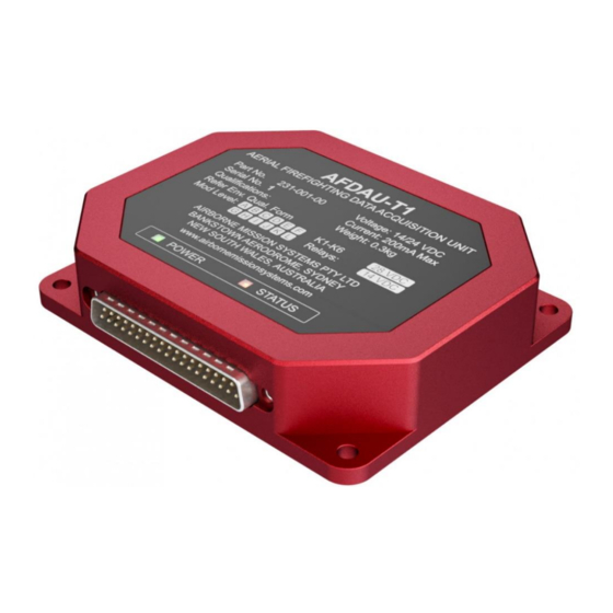
Description Introduction This manual provides a description of the AMS AFDAU-T1 Aerial Firefighting Data Acquisition Unit and instructions for installation to fixed- and rotary-wing aircraft. Before commencing installation of the AFDAU-T1 please ensure this installation manual has been read and the requirements understood. - Page 8 HEARTBEAT: Indicates a corrupt configuration, the unit is in a suspended operation state until a new configuration is written using the AFDAU-T1 Configuration Tool. P1 MAIN CONNECTOR Main I/O connector PROGRAMMING PORT Used to connect to a PC running the AFDAU-T1 Configuration Tool. AMS-IM-1-01 Rev. 7 22 September 2021...
-
Page 9: Events
When the AFDAU-T1 is configured for a rotary-wing airframe and connected to a modem, it will process hover start and stop messages. For modem connection information refer Section 2.2.11. HOVER Hover Start Hover Stop AMS-IM-1-01 Rev. 7 22 September 2021... -
Page 10: Fill
On single container aircraft, the container type is automatically detected and will reflect the container on which the fill event was generated. On dual container (bucket and tank) rotary-wing aircraft the container type is selected via a Container Select (refer Section 2.2.8) discrete input. AMS-IM-1-01 Rev. 7 22 September 2021... - Page 11 AFDAU-T1 Aerial Firefighting Data Acquisition Unit Installation Manual Application: TracPlus Pro 3 FILL FILL VOLUME TYPICAL DISPLAY OF FILL MESSAGES FIXED WING ROTARY WING AMS-IM-1-01 Rev. 7 22 September 2021...
-
Page 12: Drop Start
The ID of the drop pair. This value is unique to each Drop Start and Drop Stop pair to help agencies match each drop start and stop event. This value is sequential for each drop and resets when the AFDAU-T1 is restarted. AMS-IM-1-01 Rev. 7 22 September 2021... -
Page 13: Drop Stop
The ID of the drop pair. This value is unique to each Drop Start and Drop Stop that are a pair to help agencies match each drop start and stop event. This value resets when the AFDAU-T1 is reset. AMS-IM-1-01 Rev. 7 22 September 2021... - Page 14 On single container aircraft, the container type is automatically detected and will reflect the container on which the fill event was generated. On dual container rotary-wing aircraft the container type is selected via a Container Select (refer Section 2.2.8) discrete input. Application: TracPlus Pro 3 DROP STOP DROP VOLUME AMS-IM-1-01 Rev. 7 22 September 2021...
- Page 15 AFDAU-T1 Aerial Firefighting Data Acquisition Unit Installation Manual TYPICAL DISPLAY OF DROP MESSAGES FIXED WING ROTARY WING AMS-IM-1-01 Rev. 7 22 September 2021...
-
Page 16: Specifications
Red anodised machined aluminium chassis with black anodised backplate and Autotex F200 Polyester electric lighted fascia. Connectors 37 pin male D-Subminiature (J1) Environmental Specifications Environmental Qualifications Limitations Volume Gauging System Minimum gauged volume must be 500L or less. AMS-IM-1-01 Rev. 7 22 September 2021... -
Page 17: Installation Overview
CAUTION IT IS NOT RECOMMENDED TO USE A TORQUE SWITCH COMMON ON SOME FIXED WING AIRCRAFT AS RESULTS ARE NOT RELIABLE. INSTALLATION OF AN AIRSPEED SWITCH IS RECOMMENDED. AMS-IM-1-01 Rev. 7 22 September 2021... -
Page 18: Container Door Open
This connection is not required when only interfacing to a Helitak Tank PLC. This data is supplied via the Helitak Tank RS-232 protocol. For all other installations including a dual Helitak tank and bucket installation, connection is required. AMS-IM-1-01 Rev. 7 22 September 2021... -
Page 19: Premix Select
The AFDAU-T1 can be configured for a discrete switched signal that tells the AFDAU-T1 to change from WATER type to the additive type selected by the Additive Select input (see section 2.2.6) on one of either the 6 Relays or the 6 GPI inputs. AMS-IM-1-01 Rev. 7 22 September 2021... -
Page 20: Container Select
Typically, this would be connected to an existing landing gear stowed indicator light or other electrical indication of landing gear position. Refer to section 2.3 for guidance on how to connect this input. AMS-IM-1-01 Rev. 7 22 September 2021... -
Page 21: Container Volume
C40 Indicator Description RS232 TX Shield * RS232 Ports 1-4 may be used of the AFDAU-T1. Port 4 is shown above. MSI Load Cell w/ MSI-150XM Indicator Pinouts AFDAU-T1 150XM Description Serial Data Signal Return AMS-IM-1-01 Rev. 7 22 September 2021... - Page 22 AFDAU-T1 to account for this ungaugable quantity. Refer Section 5.4. Helitak Tank PLC Pinouts AFDAU-T1 Helitak PLC Description 9-Pin D-Sub * RS232 Ports 1-4 may be used of the AFDAU-T1. Port 4 is shown above. AMS-IM-1-01 Rev. 7 22 September 2021...
-
Page 23: Modems
* RS232 Ports 1-4 may be used of the AFDAU-T1. Port 2 is shown above. CAUTION THE AFDAU-T1 IS SUPPORTED ON PLATFORM 3 AND 4 OF THE DZMX ONLY. CONTACT FLIGHTCELL FOR MORE INFORMATION. AMS-IM-1-01 Rev. 7 22 September 2021... -
Page 24: Discrete Sensors
There are two ways in which to use the relays, by switching the ground pin or by switching the power pin as demonstrated below: EXAMPLE: GROUND SWITCHED RELAY AFDAU-T1 DISCRETE SIGNAL PROCESSOR Discrete Sensor +28vdc K1-K6 EXAMPLE: POWER SWITCHED RELAY AFDAU-T1 DISCRETE SIGNAL PROCESSOR +28vdc Discrete Sensor K1-K6 AMS-IM-1-01 Rev. 7 22 September 2021... - Page 25 Engine OFF event. The AFDAU does not suffer this issue and handles this problem through its firmware, no additional circuitry such as additional relays are required, using an internal relay provided in the AFDAU is sufficient. AMS-IM-1-01 Rev. 7 22 September 2021...
-
Page 26: General Purpose Inputs
EXAMPLE: RELAY CIRCUIT IN PARALLEL W/ GPI +28VDC AFDAU-T1 DISCRETE SIGNAL PROCESSOR GPI_1 - GPI_6 Discrete Sensor Existing relay circuit GPI Connection Pinouts Main Connector (J1) GPI Pins Description GPI_1 GPI_2 GPI_3 GPI_4 GPI_5 GPI_6 Switch to Ground AMS-IM-1-01 Rev. 7 22 September 2021... -
Page 27: Configuration Overview
Flightcell DZMx. Provides the following data: • Delivery of AFDAU-T1 Event Messages • GPS Position Remote Do not configure Reabe Gauge Volume communication protocol for interfacing to Reabe Main and Remote indicators. Provides the following data: • Container Volume AMS-IM-1-01 Rev. 7 22 September 2021... -
Page 28: Legacy Loadcell Interface
THIS OFFSET VALUE IS FOR FINE TUNING ONLY AND IS NOT A COMPENSATION FOR AN INCORRECTLY OR UNCALIBRATED REABE PROBE SYSTEM. INPUTING LARGE VALUES (TYPICALLY ABOVE 500 LITRES) WILL ADVERSELY AFFECT THE ACCUARCY OF VOLUMES IN EVENT REPORTS. AMS-IM-1-01 Rev. 7 22 September 2021... -
Page 29: Airframe Inputs
• Foam or Gel Inject Switch for bucket additive inject system Tank Additive Refer Section 2.2.6 Inject Detects Additive Inject command from Pilot. Connects to: • Hopper (Fixed-Wing) Foam or Gel Inject Switch or, AMS-IM-1-01 Rev. 7 22 September 2021... - Page 30 Always Bucket – Leave configured. • Always Tank – Permanently ground GPI pin and configure for Container Type Note: For fixed-wing aircraft always leave this airframe input UNCONFIGURED. Landing Gear Up Refer Section 2.2.8 Float-plane type aircraft only AMS-IM-1-01 Rev. 7 22 September 2021...
-
Page 31: Installation Procedures
182-8490 Standard Procedures Installation is to be carried out in accordance with the instructions included in this manual, or later revision. AMS accepts no liability arising from installations deviating from the installation described herein. Unless otherwise stated, adhere to the standard practices described in FAA AC 43.13-1B, Acceptable Methods Techniques, and Practices –... -
Page 32: Post Installation Procedures
4. Under the Modem heading in the Diagnostics Tool ensure a Latitude and Longitude are displayed and check to ensure they make sense for your current location. (Expect large inaccuracies if carrying out checks inside a hangar, a clear view of the sky may be required if unable to acquire position). AMS-IM-1-01 Rev. 7 22 September 2021... - Page 33 The following procedure is general and applicable to all types of volume sensors however it is impractical for load cell type sensors without additional hardware. AMS does NOT recommend suspending loads from the aircraft cargo hook for the purposes of testing the AFDAU-T1 installation.
-
Page 34: Configuration And Firmware Update
USB A to USB Mini B Cable (supplied with installation kit). • Computer running Windows 10 operating system (see note below) with AFDAU Config Tool installed. CAUTION THE AFDAU-T1 CURRENTLY ONLY COMMUNICATES WITH WINDOWS 10 COMPUTERS. WE ARE WORKING TO RESOLVE THIS ISSUE. AMS-IM-1-01 Rev. 7 22 September 2021... -
Page 35: Installing The Afdau Config Tool
2. If a prompt appears asking if you want to allow access to an app from an unknown publisher select yes from the options. Wait for the installation to complete. AMS-IM-1-01 Rev. 7 22 September 2021... -
Page 36: Updating The Afdau-T1 Firmware
USB end into a port on your laptop. 2. Click the arrow next to the AMS logo to drop down the menu and select “Load 4. When detected, the AFDAU-T1 port will be available in the dropdown box at Firmware”. - Page 37 6. Once connected, the port status bar will change to a green CONNECTED message and the ON DEVICE Version will change from <no device> to the that you have been given or that you have downloaded. firmware level currently on the unit. AMS-IM-1-01 Rev. 7 22 September 2021...
- Page 38 11. Once the firmware has loaded, a box will appear telling you your upload was successful. Click OK to continue. The AFDAU will reboot. The red light on the AFDAU will be solid during the reboot. AMS-IM-1-01 Rev. 7 22 September 2021...
-
Page 39: Configuring The Afdau-T1
USB end into a port on your laptop. 2. Click the arrow next to the AMS logo to drop down the menu and select 4. When detected, the AFDAU-T1 port will be available in the dropdown box at “Configure”. - Page 40 9. Click OK and the configuration fields will be populated with the current previously saved “.cfg” file or use the dropdown fields to set the configuration configuration on the connected AFDAU. as required to match your installation. AMS-IM-1-01 Rev. 7 22 September 2021...
- Page 41 12. Fill out the configuration fields. Refer to Section 3 for more information and select the desired “.cfg” file. about each configuration field. 11. Click OK and the configuration fields will be populated with the configuration contained in the opened file. AMS-IM-1-01 Rev. 7 22 September 2021...
- Page 42 17. Once the configuration has loaded, a box will appear telling you your upload button. was successful. Click OK to continue. The AFDAU will reboot. The red light on the AFDAU will be solid during the reboot. AMS-IM-1-01 Rev. 7 22 September 2021...
-
Page 43: Configuring The Rockair
Serial Mode – Serial API • Baud Rate – 9600 • Sample Rate – 5 sec 4. Wait until the entries change (can take a few seconds) to confirm configuration has been correctly set. AMS-IM-1-01 Rev. 7 22 September 2021... -
Page 44: Configuring The Dzmx
Press MENU > Hardware Config > Debug Port Config > (Select AFDAU) 3. To configure via the DZMx Manager: a. Login > Authenticate as Installer b. Settings > Hardware > External > Debug Port Config > (Select AFDAU) AMS-IM-1-01 Rev. 7 22 September 2021... -
Page 45: Configuring The Msi-1 Indicator
Configuring the MSI-1 Indicator The MSI-1 may not be configured by default to output serial data on Port 1. Consult the manufacturer and any applicable airworthiness authority for approval to change the configuration of this device. AMS-IM-1-01 Rev. 7 22 September 2021... -
Page 46: Troubleshooting
2. An internal fault has 1 minute) occurred in the AFDAU-T1. Contact AMS for repair. The Status (Amber) light is not on. The unit has an internal fault 1. An internal fault has The Power (Green) light is on. -
Page 47: Mechanical Drawings
AFDAU-T1 Aerial Firefighting Data Acquisition Unit Installation Manual Mechanical Drawings AMS-IM-1-01 Rev. 7 22 September 2021... -
Page 48: Connector Pinouts
14 or 28 VDC Relay, +ve side of coil side of coil K6 RELAY GROUND 14 or 28 VDC Relay, -ve K6 RELAY POWER 14 or 28 VDC Relay, +ve side of coil side of coil AMS-IM-1-01 Rev. 7 22 September 2021... -
Page 49: Wiring Diagrams
Container Interface ............................51 Container Interface – Buckets ......................... 52 Volume Sensor Interface – Reabe Probe System .................... 53 Volume Sensor Interface – Loadcell Indicator Interfaces ................54 Volume Sensor Interface – Helitak Tank ......................55 AMS-IM-1-01 Rev. 7 22 September 2021... -
Page 50: Wiring Installation Considerations
4. WIRING LOOMS ARE TO BE SUPPORTED AT INTERVALS NO GREATER THAN 600MM (24"). ADHERE TO CLAMPING AND SEPARATION REQUIREMENTS OF AIRCRAFT PUBLICATIONS OR FAA AC 43.13- 1B CHANGE 1 PARAGRAPH 11-146.ROUTE WIRES IN ACCORDANCE WITH AIRCRAFT PUBLICATIONS. AMS-IM-1-01 Rev. 7 22 September 2021... -
Page 51: Modem Interface - Rockair
AFDAU-T1 Aerial Firefighting Data Acquisition Unit Installation Manual Modem Interface – RockAIR AMS-IM-1-01 Rev. 7 22 September 2021... -
Page 52: Modem Interface - V2Track
AFDAU-T1 Aerial Firefighting Data Acquisition Unit Installation Manual Modem Interface – v2track AMS-IM-1-01 Rev. 7 22 September 2021... -
Page 53: Modem Interface - Dzmx
AFDAU-T1 Aerial Firefighting Data Acquisition Unit Installation Manual Modem Interface – DZMx AMS-IM-1-01 Rev. 7 22 September 2021... -
Page 54: Additive Interface - Helicopter Typical Installation
AFDAU-T1 Aerial Firefighting Data Acquisition Unit Installation Manual Additive Interface – Helicopter Typical Installation AMS-IM-1-01 Rev. 7 22 September 2021... -
Page 55: Additive Interface - Helicopter Sei Sacksafoam Controller
AFDAU-T1 Aerial Firefighting Data Acquisition Unit Installation Manual Additive Interface – Helicopter SEI Sacksafoam Controller AMS-IM-1-01 Rev. 7 22 September 2021... -
Page 56: Additive Interface - Fixed Wing Typical Installation
AFDAU-T1 Aerial Firefighting Data Acquisition Unit Installation Manual Additive Interface – Fixed Wing Typical Installation AMS-IM-1-01 Rev. 7 22 September 2021... -
Page 57: Container Interface
AFDAU-T1 Aerial Firefighting Data Acquisition Unit Installation Manual Container Interface AMS-IM-1-01 Rev. 7 22 September 2021... -
Page 58: Container Interface - Buckets
AFDAU-T1 Aerial Firefighting Data Acquisition Unit Installation Manual Container Interface – Buckets AMS-IM-1-01 Rev. 7 22 September 2021... -
Page 59: Volume Sensor Interface - Reabe Probe System
AFDAU-T1 Aerial Firefighting Data Acquisition Unit Installation Manual Volume Sensor Interface – Reabe Probe System AMS-IM-1-01 Rev. 7 22 September 2021... -
Page 60: Volume Sensor Interface - Loadcell Indicator Interfaces
AFDAU-T1 Aerial Firefighting Data Acquisition Unit Installation Manual Volume Sensor Interface – Loadcell Indicator Interfaces AMS-IM-1-01 Rev. 7 22 September 2021... -
Page 61: Volume Sensor Interface - Helitak Tank
AFDAU-T1 Aerial Firefighting Data Acquisition Unit Installation Manual Volume Sensor Interface – Helitak Tank AMS-IM-1-01 Rev. 7 22 September 2021...
Need help?
Do you have a question about the AFDAU T-1 and is the answer not in the manual?
Questions and answers