Table of Contents
Advertisement
Quick Links
Document History
Revision
Date
1.0
April 14, 2020
1.1
April 29, 2020
1.2
May 12, 2020
For questions or help contact your local sales rep or reach out to us at:
SmartStep
Quick Start Guide and User Manual
Notes
Initial Release. Support of Firmware Version 1.4.1
Added Information to support Firmware Version 1.4.2
Added Information to support Firmware Version 1.5.1
314-432-3282
sales@update-systems.com
joe@update-systems.com
™
Actuator
Advertisement
Table of Contents

Related Manuals for usi SmartStep


Summary of Contents for usi SmartStep
- Page 1 ™ SmartStep Actuator Quick Start Guide and User Manual Document History Revision Date Notes April 14, 2020 Initial Release. Support of Firmware Version 1.4.1 April 29, 2020 Added Information to support Firmware Version 1.4.2 May 12, 2020 Added Information to support Firmware Version 1.5.1...
- Page 2 Quick Start Guide Device Defaults The SmartStep actuator ships with the following defaults: Range: 0-90° 4-20mA calibrated with 20mA set as OPEN and 4mA set as CLOSED Rotation Speed set to 70% of maximum Custom Setup The SmartStep Actuator was designed to have a known zero position to make set up out of box as smooth as possible.
- Page 3 Automatic Modes of Operation Quick Start Guide There are six automatic modes of operation. Each are outlined below. 4-20mA: IN + / IN - : Insert 4-20 mA or 0-10 V control Two-wire: Neutral Wire Inserted in to COM; Positive signal into appropriate terminal.
-
Page 4: Table Of Contents
3.1 Position Setup Screen and Calibration Section 3: Module Configuration 3.2 Initial Calibration 3.3 FAILSAFE Setup 3.4 RANGE CONTROL Setup 3.5 MODBUS Setup & Operation MODBUS RTU Mode MODBUS TCP Mode MODBUS TCP Mode 3.6 MODBUS Register Reference SmartStep User Guide ver 1.2... -
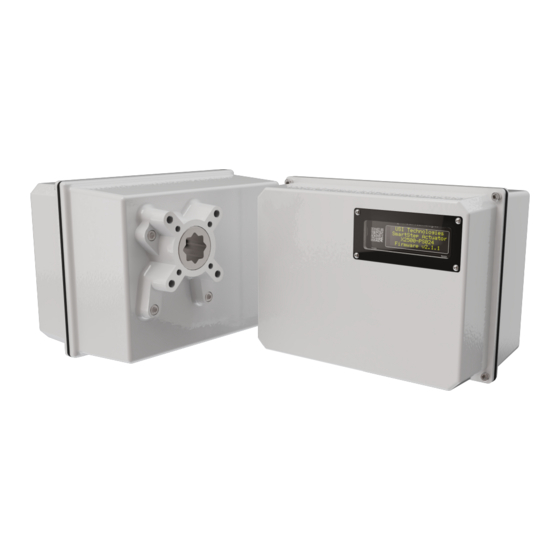
Page 5: Section 1: Hardware Overview
Clockwise or CounterClockwise is mentioned, it is always from the zero point as shown to the left when viewing the actuator as shown. 180° 180° 270° 90° 270° 90° 0° Counter 0° Clockwise Clockwise SmartStep User Guide ver 1.2... -
Page 6: Keypad And Button Reference
In Manual Mode, press to rotate counterclockwise by 0.1° In Manual Mode, press to rotate clockwise by 0.1° From Main Screen, enter Calibration Mode When in Calibration Mode clears CLOSE calibration point When in Calibration Mode clears OPEN calibration point SmartStep User Guide ver 1.2... -
Page 7: Wiring Reference
NEC. (UL) MOTOR: ▪ Pre-assembled 4-pin connector that supplies drive current to the stepper motor USB: • Used to update module firmware and communication SUPER CAP • Supplied communication link to Super Cap module if installed SmartStep User Guide ver 1.2... -
Page 8: Section 2: Menu Navigation And Status Screens
Information Screens Diag#3 Parameter Screens that may be edited 2.1 Module Configuration Screen Map To configure the SmartStep Actuator hold down ESC and press the RIGHT Arrow button while on the MAIN screen to enter the config menu 4-20mA Position... -
Page 9: Main Screen Elements
Accessed by pressing from the MAIN screen. If Super Cap module is installed this screen shows individual charge levels for each capacitor. If Super Cap module is not installed, all levels will be shown as 0. SmartStep User Guide ver 1.2... -
Page 10: Diagnostics 2 Screen
MAIN screen. Model as defined in Model Setup Screen Loaded Firmware version 2.7 Restore Defaults Screen Accessed by pressing from the splash screen. Follow prompts on screen to restore the unit to factory default settings. SmartStep User Guide ver 1.2... -
Page 11: Model Setup Screen
All SmartStep actuators are have absolute position where 0° is always Please Note: down and Counter-clockwise direction is always increasing from 0°. -
Page 12: Initial Calibration
Press ENT again to set RANGE CONTROL mode when proper selection is made. • CW - Valve always moves CLOCKWISE to OPEN position • CCW - Valve always moves COUNTERCLOCKWISE to OPEN position SmartStep User Guide ver 1.2... -
Page 13: Modbus Setup & Operation
Slave Receive Timeout Trips. Select value of 1- 20 seconds or disable by selecting NONE MODBUS TCP Mode Press the ENT button to enter edit mode. Use UP/ DOWN Arrows to enable or disable DHCP. Press ENT again to save settings. SmartStep User Guide ver 1.2... -
Page 14: Modbus Register Reference
40002 ushort 70%) Max Close Speed (%/10 of Max Valve Speed) (1 - 10) (Default: 7 or 40003 ushort 70%) Acc/Decel Span (Degree Range for Acceleration and Deceleration) (1o - 40004 ushort 10o) (Default: 5) SmartStep User Guide ver 1.2...
Need help?
Do you have a question about the SmartStep and is the answer not in the manual?
Questions and answers