Table of Contents
Advertisement
Quick Links
Advertisement
Table of Contents

Subscribe to Our Youtube Channel
Related Manuals for PCB Piezotronics 130E20


Summary of Contents for PCB Piezotronics 130E20
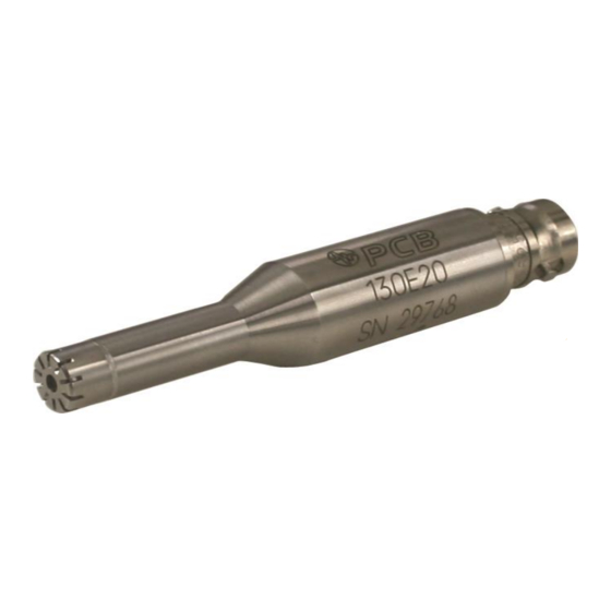
- Page 1 Model 130E20 ICP® Electret Array Microphone Installation and Operating Manual For assistance with the operation of this product, contact PCB Piezotronics, Inc. Toll-free: 800-828-8840 24-hour SensorLine: 716-684-0001 Fax: 716-684-0987 E-mail: info@pcb.com Web: www.pcb.com...
- Page 2 Returning Equipment – Following the equipment to PCB Piezotronics for these procedures will insure that your repair. User servicing or repair is not returned materials are handled in the recommended and, if attempted, may most expedient manner.
- Page 3 PCB Piezotronics, Inc. Warranty – All equipment and repair 3425 Walden Ave. services provided by PCB Piezotronics, Depew, NY 14043 USA Inc. are covered by a limited warranty Toll-free: (800) 828-8840 against defective...
-
Page 4: Table Of Contents
OPERATING GUIDE FOR 130 SERIES MICROPHONES Contents: 1.0 Introduction ....... 1 2.0 Product Description ....1 130E20 3.0 Powering ........2 4.0 Installation and Operation ..3 5.0 Calibration ......... 3 6.0 Service ........5 7.0 Warranty ........5 130E21... -
Page 5: Powering
These Microphones are 7mm in diameter and have a dynamic range up to 122dB. The 130E20 includes a BNC Jack, 130E21 includes a 10-32 Coaxial Jack, and the 130E22 and 130A23 both include a SMB Coaxial Socket. All 130 series Microphones are Prepolarized. -
Page 6: Installation And Operation
signal conditioner provides a zero-based, AC-coupled, output signal that is compatible with most standard readout devices. Many FFT analyzers, data acquisition modules, and data collectors have the proper constant- current excitation built-in for direct use with ICP microphones. Before using this feature, make sure the supply voltage and constant current are within acceptable limits for use with your particular microphone. -
Page 7: Calibration Certificate
Calibration ratios for these types of devices are limited to 1:1. 5. See M anufacturer’s Specification Sheet for a detailed listing of performance specifications. 6. This certificate shall not be reproduced, except in full, without written approval from PCB Piezotronics, Inc 7. Calibrated per ACS-21. -
Page 8: Service
(716-684-0001) to discuss your immediate dynamic instrumentation needs with a PCB Application Engineer. 7.0 Warranty All equipment and repair services provided by PCB Piezotronics, Inc. are covered by a limited warranty against defective material and workmanship for a period of one year. Visit www.PCB.com for a complete statement of our warranty. - Page 9 Model Number Revision: F ICP® ELECTRET ARRAY MICROPHONE 130E20 ECN #: 42672 Performance ENGLISH OPTIONAL VERSIONS Nominal Microphone Diameter 1/4" 1/4" Optional versions have identical specifications and accessories as listed for the standard model Frequency Response Characteristic(at 0° incidence) Free-Field Free-Field except where noted below.
Need help?
Do you have a question about the 130E20 and is the answer not in the manual?
Questions and answers