Advertisement
Available languages
Available languages
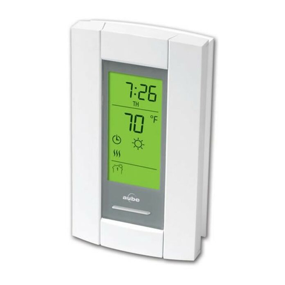
PB112C-GA & PB112C-GB
INSTALLING AND TESTING A GROUND FAULT
PROTECTION THERMOSTAT
READ THE ENTIRE DOCUMENT BEFORE STARTING
CAUTION
• Installation must be carried out by an electrician and must
comply with national and local electrical codes.
• Use this thermostat only for resistive load.
• Do NOT install the thermostat in an area where it can be
exposed to water or rain.
• To prevent severe shock or electrocution, always turn the
power OFF at the service panel before working with wiring.
• Install the thermostat onto an electrical box.
• Use special CO/ALR solderless connectors if you connect
the thermostat to aluminum wires.
• The thermostat is made up of two components: the control
module (faceplate) and the power base. If you install
another control module, ensure it is configured for 15-
minute cycles.
Ground Fault Protection
This thermostat is equipped with ground fault protection. In the
event of a ground fault, the ground fault protection mechanism
on the thermostat trips and quickly stops the flow of electricity
to prevent serious injury.
Definition of a ground fault
Instead of following its normal safe path, electricity passes
through a person's body to reach the ground. For example, a
defective floor heating mat can cause a ground fault.
The ground fault protection does not protect against circuit
overloads, short circuits, or electrical shocks. For example,
you can still receive an electrical shock if you touch bare wires
while standing on a non-conducting surface such as a wood
floor.
Ground Fault Protection Reset
When the ground fault protection mechanism trips, the TEST
light is On (red). To reset the ground fault protection, switch
the thermostat to Standby and back to On. The TEST light will
go off.
Supplied Parts
• One (1) power base
• Two (2) mounting screws
• Four (4) solderless connectors for copper wires
• One (1) flat-tip screwdriver
Installing the Power Base
1. Turn off power to the heating system at the service
panel in order to avoid any risk of electrical shock.
2. Connect the wires using solderless connectors for cop-
per wires:
120 V
L2(N)
L1(L)
240 V
L2(N)
L1(L)
3. Insert the floor sensor cable through one of the two
openings on the base and connect the sensor wires to
terminals 1 and 2 (no polarity).
• The sensor cable must pass outside the electrical box and
follow the wall down to the floor.
• Position the sensor cable such that it does not come in
contact with the floor heating wires. The sensor must be
centered between two floor heating wires for best
temperature control.
• Do NOT staple the sensor head (the plastic end) to the floor.
Doing so might damage the sensor. Any damages might not
be noticeable during testing but can become apparent
several days later.
INSTALLATION GUIDE
Power supply
White
Black
Red
Black
L2(N)
L1(L)
Black
White
Red
Black
Power supply
Red
Black
Red
Black
L2(N)
L1(L)
Black
Red
Red
Black
Put Bar Code Here
Load
Load
Advertisement
Table of Contents

Related Manuals for Honeywell PB112C-GA


Summary of Contents for Honeywell PB112C-GA
- Page 1 PB112C-GA & PB112C-GB INSTALLING AND TESTING A GROUND FAULT PROTECTION THERMOSTAT INSTALLATION GUIDE READ THE ENTIRE DOCUMENT BEFORE STARTING Installing the Power Base 1. Turn off power to the heating system at the service CAUTION panel in order to avoid any risk of electrical shock.
- Page 2 This warranty does not cover removal or reinstallation costs. This warranty shall not apply if it To ensure the ground fault protection is always in working is shown by Honeywell that the defect or malfunction was caused by damage which occurred order, test it once the thermostat is installed and on a monthly while the product was in the possession of a consumer.
- Page 3 PB112C-GA & PB112C-GB INSTALLATION ET MISE À L’ESSAI D’UN THERMOSTAT MUNI DE PROTECTION CONTRE LES FUITES À LA TERRE GUIDE D’INSTALLATION VEUILLEZ LIRE LE DOCUMENT EN ENTIER AVANT Installer la base de puissance DE COMMENCER Mettre le système de chauffage hors tension à partir du pan- neau électrique principal afin d’éviter tout risque de choc élec-...
- Page 4 Installer le module de contrôle (façade) sur la base de puis- Honeywell garantit ce produit, à l'exception des piles, contre tout vice de fabrication ou de sance. matière dans la mesure où il en est fait une utilisation et un entretien convenables, et ce, pour Mettre le système de chauffage sous tension.
Need help?
Do you have a question about the PB112C-GA and is the answer not in the manual?
Questions and answers
Que signifie le F encerclé sur mon thermostat TH101A ? What's the meaning of F on my thermostat TH101A ?
Where can I buy a new thermostat???