Table of Contents
Advertisement
Quick Links
Advertisement
Table of Contents

Related Manuals for FlameStop PFS200-2

Summary of Contents for FlameStop PFS200-2
- Page 1 Issue 1.06...
-
Page 3: Table Of Contents
PFS200-2 Intelligent FDCIE With AS4428.3-2010 Fascia Installation and Operation Manual CONTENTS Installation Precautions ....................1 Approval Information....................2 Chapter 1 Product Introduction................... 3 Chapter 2 Technical Specifications ................4 2.1 Operating Voltage ....................4 2.2 Standby Batteries ....................4 2.3 Communication Loop Parameters ................ 4 2.3.1... - Page 4 PFS200-2 Intelligent FDCIE With AS4428.3-2010 Fascia Installation and Operation Manual Chapter 5 Display and Disposal of System Information ........23 5.1 Normal Information ....................23 5.2 Fire Alarm ......................24 5.2.1 Fire Alarm Screen ................... 24 5.2.2 Disposal of Fire Alarm Signal ..............25 5.3 Fault........................
- Page 5 Specifications and particulars in relation to products referred to within are subject to change without prior notice and FlameStop Australia will not be held liable in any way for any errors or omissions. It is the responsibility of the customers to verify that a chosen product is suitable for their given application.
-
Page 6: Installation Precautions
Consult with the appropriate authority having jurisdiction for confirmation of the requirements. The PFS200-2 FDCIE shall only be installed and serviced by specially trained fire alarm system technicians. Disconnect all sources of power before servicing. Control unit and associated equipment may be damaged by removing and/or inserting cards, modules, or interconnecting cables while the unit is energized. -
Page 7: Approval Information
AS7240.2 AS7240.4 √ √ √ PFS200-2 Intelligent FDCIE complies with the requirements of AS4428.3-2010 and AS7240.2 and AS7240.4. In addition to the basic requirements of these standards, the panel conforms to the following optional requirements. Option AS 7240.2 Clause Indication... -
Page 8: Chapter 1 Product Introduction
Maximum two Class A loops. The first loop can have up to 235 addressable devices, and the second up to 242 devices. It is compatible with a series of addressable FlameStop products, which are intelligent sounder strobe (PXI-9403) complying with AS 7240.3, rate of rise and fixed temperature heat detector (PHI-9103) complying with AS 7240.5,... -
Page 9: Chapter 2 Technical Specifications
PFS200-2 Intelligent FDCIE With AS4428.3-2010 Fascia Installation and Operation Manual Chapter 2 Technical Specifications 2.1 Operating Voltage +10% Input Voltage: 220V/230VAC -15% Frequency: 50Hz/60Hz Input Current: 0.5A Fuse: 2A delay Recommended Wiring: 1.5mm or above of twin and earth cable, complying with local installation code. -
Page 10: Detection Loop Parameters
PFS200-2 Intelligent FDCIE With AS4428.3-2010 Fascia Installation and Operation Manual 2.4 Detection Loop Parameters LOOP OUT (+, -): Polarized signal cable from the FDCIE connecting up to 235 addressable devices. LOOP IN (+, -): Polarized signal cable returning to the FDCIE. -
Page 11: Dimensions
PFS200-2 Intelligent FDCIE With AS4428.3-2010 Fascia Installation and Operation Manual 2.6 Dimensions 420mm×700mm×172mm Page 6... -
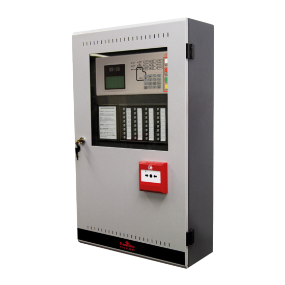
Page 12: Chapter 3 Construction And Components
PFS200-2 Intelligent FDCIE With AS4428.3-2010 Fascia Installation and Operation Manual Chapter 3 Construction and Components 3.1 Appearance and Internal Construction PFS200-2 FDCIE is flush-mounted. Its appearance and internal structure are shown in Fig. 3-1 and 3-2. Fig. 3-1 ① ②... - Page 13 PFS200-2 Intelligent FDCIE With AS4428.3-2010 Fascia Installation and Operation Manual Fig. 3-2 ① ② ③ Display control Zone indication board Printer ④ ⑤ ⑥ Intelligent manual call point Buzzer Power supply ⑦ ⑧ ⑨ Loop interface board Transformer PSU filter ⑩...
-
Page 14: Display Area
PFS200-2 Intelligent FDCIE With AS4428.3-2010 Fascia Installation and Operation Manual 3.1.1 Display Area The display area consists of clock, LCD, LED and keypad, which are shown in Fig. 3-3. Fig. 3-3 3.1.2 Description of LEDs FIRE: Red. It illuminates when the FDCIE detects an alarm condition. After fire alarm condition is removed, the fire status can only be cleared by pressing SILENCE/RESOUND ALARM then the RESET button, and this LED goes out simultaneously. -
Page 15: Description Of Buttons
PFS200-2 Intelligent FDCIE With AS4428.3-2010 Fascia Installation and Operation Manual PRE-ALARM: Red. It illuminates when there is pre-alarm message. SEVERAL ALARMS: Red. It illuminates when there is more than one device in alarm. SOUNDER FLT/DIS: Yellow. It flashes when any loop sounder is in fault. It illuminates when any loop sounder is disabled. -
Page 16: Zone Indication And Manual Interventional Panel (Zcp)
PFS200-2 Intelligent FDCIE With AS4428.3-2010 Fascia Installation and Operation Manual LOCK: Locking the keypad when it is unlocked. SYSTEM: System set-up button, used for setting system time, modifying operator password and manager password, setting network system, setting beginning zone number, setting output mode, system initialization and viewing supervisory data of addressable devices. -
Page 17: Components
PFS200-2 Intelligent FDCIE With AS4428.3-2010 Fascia Installation and Operation Manual 3.1.4.1 Zone Indication LEDs Fire: Red. It illuminates when a fire occurs in a zone. It goes out after the FDCIE has been reset. Fault/Disable: Yellow. It flashes when there is a fault with the zone. If all devices in this zone have been disabled, the LED illuminates steadily. -
Page 18: Optional Units
The FDCIE monitors the running of network cards in real time so that the card can work after being inserted. PFS200-2 provides two kinds of network cards: Local Network Card (RS485 card) and Monitor & Control Card (RS232 card). Their structures are shown in Fig. 3-6. -
Page 19: Peripheral Devices
5. 20P data cable connecting with main board. 6. Standard RS232 interface connecting with GMC. Note: You need to include an RS232 card in your first order of PFS200-2 FDCIE. Only with this card, device definition and C&E equations can be downloaded from the PC. -
Page 20: Manual Call Points
Installation and Operation Manual 3.3.4 Manual Call Points A series of manual call points (such as PXDI-9204) can be connected to the loop of PFS200-2. Fire is confirmed manually by pressing the resettable element on the MCP, alarm signal can be sent to the FDCIE. -
Page 21: Chapter 4 Installation
PFS200-2 Intelligent FDCIE With AS4428.3-2010 Fascia Installation and Operation Manual Chapter 4 Installation The steps below are guidance for installation of the FDCIE. Check if you have received all items ordered. Install the cabinet. Power up the FDCIE and carry out start-up inspection. -
Page 22: Installing The Cabinet
PFS200-2 Intelligent FDCIE With AS4428.3-2010 Fascia Installation and Operation Manual 4.2 Installing the Cabinet Mounting holes of the cabinet is shown in Fig. 4-1. Ambient conditions for installation of the FDCIE: Temperature: 0℃~+40℃ Relative humidity≤95%,non-condensing Fig. 4-1 Page 17... -
Page 23: Start-Up Check
Check if the buzzer can give loud alarm sounds. 4.4 Connections of Peripheral Devices 4.4.1 Connection of Mains Power PFS200-2 FDCIE receives power from a 220V/230VAC, 50Hz/60Hz supply. The current flows through a filter to the transformer. The transformer converts the input mains voltage to 27VAC. ... -
Page 24: Connection Of Peripheral Devices
PFS200-2 Intelligent FDCIE With AS4428.3-2010 Fascia Installation and Operation Manual 4.4.3 Connection of Peripheral Devices Caution: Do not connect power to your device until you have completed all input and output connections. Failure to do so may result in injury! Terminals of loop interface board are shown in Fig. - Page 25 PFS200-2 Intelligent FDCIE With AS4428.3-2010 Fascia Installation and Operation Manual Output 24VDC Normally Closed Normally Open Short Pins - 1 to 2 & Short Pins - 3 to 4 & Short Pins - 2 to 3 & 4 to 5 of X1...
- Page 26 PFS200-2 Intelligent FDCIE With AS4428.3-2010 Fascia Installation and Operation Manual RS-485 (XT11, XT12): Connection between repeater panel/s and FDCIE. Earth (X8): This terminal is for checking earth fault when connected. DISABLE OUTPUT, SOUNDER CIRCUIT OUTPUT and FIRE ALARM OUTPUT can provide three output modes, which are 24VDC voltage output, normally open output and normally closed output.
-
Page 27: Connection Checking And Device Registration
PFS200-2 Intelligent FDCIE With AS4428.3-2010 Fascia Installation and Operation Manual 4.4.3.3 Connection of Communication Loop Network Maximum 32 FDCIEs (XT11) Repeater Maximum 10 Repeater Panels (XT12) Fig. 4-8 4.5 Connection Checking and Device Registration 4.5.1 Connection Checking Check the circuit connected with the FDCIE. Measure the insulation resistance between loops and between loops and ground, which should be more than 20MΩ. -
Page 28: Chapter 5 Display And Disposal Of System Information
Chapter 5 Display and Disposal of System Information PFS200-2 can be started after installation according to description in Chapter 4. Turn on the power supply to panel, then turn the main and standby power switch on the FDCIE, the FDCIE executes self-test and enter normal standby state. -
Page 29: Fire Alarm
PFS200-2 Intelligent FDCIE With AS4428.3-2010 Fascia Installation and Operation Manual 5.2 Fire Alarm 5.2.1 Fire Alarm Screen FIRE LED is lit when there is fire alarm signal. Buzzer of the FDCIE sounds (fire truck sound), and corresponding FIRE LED on the ZCP is also lit. -
Page 30: Disposal Of Fire Alarm Signal
PFS200-2 Intelligent FDCIE With AS4428.3-2010 Fascia Installation and Operation Manual 5.2.2 Disposal of Fire Alarm Signal When a fire alarm occurs, first find out the location according to the information shown on the FDCIE, to verify whether it is a true fire alarm. - Page 31 PFS200-2 Intelligent FDCIE With AS4428.3-2010 Fascia Installation and Operation Manual The LCD displays “Key fault”. The panel generates continuous alarm sound. Fault relay outputs. The keypad cannot be used. The panel can monitor fire alarm.
-
Page 32: Disposal Of Fault Message
PFS200-2 Intelligent FDCIE With AS4428.3-2010 Fascia Installation and Operation Manual 5.3.2 Disposal of Fault Message There are two kinds of fault message. One is system fault, like power fault, and loop fault. The other is field device fault, like fault with detectors and modules etc. -
Page 33: Chapter 6 Description Of System Operation
PFS200-2 Intelligent FDCIE With AS4428.3-2010 Fascia Installation and Operation Manual Chapter 6 Description of System Operation 6.1 Keypad 6.1.1 Keypad Functions Most of the buttons have double functions. Lower mark is a character and upper mark is a command that is only activated in monitoring state. Most functional buttons are controlled by password. -
Page 34: User Operation Instruction (No Password Requirement)
PFS200-2 Intelligent FDCIE With AS4428.3-2010 Fascia Installation and Operation Manual 6.2 User Operation Instruction (No Password Requirement) 6.2.1 Changing displayed time The clock usually displays in hour and minute. In normal monitoring state, pressing ENTER, month and date are displayed. Pressing ENTER again or after a minute, hour and minute is displayed again. - Page 35 PFS200-2 Intelligent FDCIE With AS4428.3-2010 Fascia Installation and Operation Manual L1N001 Optical // Loop number, device address and device type. Zone: 01 office1 // Zone number, and zone position description. NO.001 Optical // Device address, device type.
- Page 36 PFS200-2 Intelligent FDCIE With AS4428.3-2010 Fascia Installation and Operation Manual 2 (Group) (012)(020) // 2 groups are defined. There are 12 addressable devices on Loop 1, and 20 on Loop 2. Group:01 office 1 // Zone number and location of the zone ...
- Page 37 PFS200-2 Intelligent FDCIE With AS4428.3-2010 Fascia Installation and Operation Manual Entering No. 7 to choose “7: Browsing C&E” will enter the screen for browsing C&E equation, as shown in Fig. 6-9. Browse C&E ENTER Sum: 003 C&E 001 C&E 002 C&E 003...
- Page 38 PFS200-2 Intelligent FDCIE With AS4428.3-2010 Fascia Installation and Operation Manual 6.2.2.4 Browsing history log Pressing LOG, the FDCIE enters the state of browsing history record. Using △ = and = ▽ , you can browse every item, the screen is shown in Fig. 6-10.
-
Page 39: Silencing The Panel
PFS200-2 Intelligent FDCIE With AS4428.3-2010 Fascia Installation and Operation Manual 001 of 002 Disable 12:01 Zone:005 Z-005 029/029 Zone Fully Disabled Fig. 6-12 001 of 002 Disable 12:01 // There are devices from 2 zones that are disabled, and this is the first zone. -
Page 40: Alarm Silence
PFS200-2 Intelligent FDCIE With AS4428.3-2010 Fascia Installation and Operation Manual 6.3.2 Alarm Silence Pressing SILENCE/RESOUND ALARM button can silence all sounders in the system, and light the SILENCE indicator. The silenced sounders will re-sound on receiving a new alarm. SILENCE indicator will go out when RESET button is pressed for reset, or when EVAC button is pressed for evacuation, or when a new device reports a fire. - Page 41 PFS200-2 Intelligent FDCIE With AS4428.3-2010 Fascia Installation and Operation Manual Disabling a zone Entering number “1” in the screen of Fig. 6-15 will enter disable screen as shown in Fig. 6-16. Disabling a zone Zone: 000 Fig. 6-16 Entering a 3-digit zone number and Pressing ENTER button to confirm will disable all devices of the zone.
- Page 42 PFS200-2 Intelligent FDCIE With AS4428.3-2010 Fascia Installation and Operation Manual Disable Z000 C000 T00 NoDefine Fig. 6-19 Enter a 3-digit zone number or “*” (by pressing DISABLE) at the cursor position after letter “Z”. Enter a 3-digit device address or “*” (by pressing DISABLE) at the cursor position after letter “C”.
-
Page 43: User Mode
PFS200-2 Intelligent FDCIE With AS4428.3-2010 Fascia Installation and Operation Manual In this screen, the SOUNDER CIRCUIT OUTPUT on the loop interface board can be disabled or enabled. 6.3.4.4 Disabling/Enabling Delays Inputting number 4 in the screen shown in Fig. 6-14 can enter the screen of disabling/enabling delays, as shown in Fig. - Page 44 PFS200-2 Intelligent FDCIE With AS4428.3-2010 Fascia Installation and Operation Manual In this screen, the user can setup the screen contrast, display mode, printing mode and pre-alarm mode, and can also start or stop devices. 6.3.5.1 LCD Contrast Setup Entering 1 in Fig. 6-24 will enter the screen for setting up LCD contrast, as shown in Fig. 6-25.
- Page 45 PFS200-2 Intelligent FDCIE With AS4428.3-2010 Fascia Installation and Operation Manual 6.3.5.4 Positive Alarm Sequence (PAS) Setup Entering 4 in the screen of Fig. 6-24 will enter the screen for setting up pre-alarm screen, as shown in Fig. 6-28. *PAS Mode*...
-
Page 46: Device Start/Stop Through Zcp
PFS200-2 Intelligent FDCIE With AS4428.3-2010 Fascia Installation and Operation Manual 6.3.5.6 Manual Stop of Loop Devices Entering 6 in the screen of Fig. 6-24 will enter the screen for manual stop of a loop devices. The method for stopping a device is the same as starting a device. - Page 47 PFS200-2 Intelligent FDCIE With AS4428.3-2010 Fascia Installation and Operation Manual Entering the zone to test in this screen and pressing ENTER to confirm, the zone will enter test mode, and the corresponding ZCP and TEST MODE indicators will illuminate. 6.3.7.3 Exiting Single-zone Testing Mode Entering 3 in the screen of Fig.
-
Page 48: Instructions For System Administrator (Manager Password Required)
PFS200-2 Intelligent FDCIE With AS4428.3-2010 Fascia Installation and Operation Manual 6.4 Instructions for System Administrator (Manager Password Required) Press SYSTEM to enter the system setting screen. The screen is shown in Fig. 6-35. *System Mode* 1. Time/Date 2. Password Change 3.... -
Page 49: Network Setup
PFS200-2 Intelligent FDCIE With AS4428.3-2010 Fascia Installation and Operation Manual Modify Password Input password ******** Fig. 6-38 After the password (8 digits from 0-9) is input, the LCD will display the screen shown in Fig. 6-39, requesting to confirm password. -
Page 50: Setting Up Beginning Zone Number
PFS200-2 Intelligent FDCIE With AS4428.3-2010 Fascia Installation and Operation Manual You can set the panel’s network address by entering number 1, as shown in Fig. 6-42. *Net Local Address* Please Input: 01 Range 1-32 Fig. 6-42 You can set the panel to display network message or not by entering number 2, as shown in Fig. -
Page 51: Customize
PFS200-2 Intelligent FDCIE With AS4428.3-2010 Fascia Installation and Operation Manual 6.4.5 Customize Entering number 5 in the screen in Fig. 6-35 will enter the customize screen, as shown in Fig. 6-45. *Customize* 1. Outputs Setup 2. PAS Delay 3. Resound Configure Fig. -
Page 52: System Initialization
PFS200-2 Intelligent FDCIE With AS4428.3-2010 Fascia Installation and Operation Manual 6.4.5.2 PAS Delay Time Setup Entering 2 in the screen of Fig. 6-45 will enter the screen for setting up PAS delay time, as in Fig. 6-47. *PAS Delay Time*... - Page 53 PFS200-2 Intelligent FDCIE With AS4428.3-2010 Fascia Installation and Operation Manual Equipment Num:001 Order Number:002 Fig. 6-49 Different number buttons represent different commands: “0” represents the command “Polling”. If the displayed value is between 450~650, the device is in normal operation; if it’s between 900~1200, the device is in alarm status, and if it’s between 0~120, the device is in fault.
-
Page 54: Chapter 7 Standby Battery Calculations
PFS200-2 Intelligent FDCIE With AS4428.3-2010 Fascia Installation and Operation Manual Chapter 7 Standby Battery Calculations The formula for calculating batteries capacity in accordance with AS 1670.1-2004 is as follows: = 1.25 [(I ) + F Where: = battery capacity in Ah at 20 h discharge rate... -
Page 55: Chapter 8 Maintenance
PFS200-2 Intelligent FDCIE With AS4428.3-2010 Fascia Installation and Operation Manual Chapter 8 Maintenance The FDCIE shall only be repaired by specially trained technicians. Please disconnect the power before servicing. 8.1 Replacing the Battery Type of battery: Sealed lead-acid battery Recommended period for replacing the battery: 2 years (25℃) -
Page 56: Troubleshooter
PFS200-2 Intelligent FDCIE With AS4428.3-2010 Fascia Installation and Operation Manual 8.3 Troubleshooter Problems Possible Causes Solutions No indication on a. AC input fuse blown a. Replace fuse. the panel or b. Power is abnormal b. Check and replace low-voltage abnormal switch power. -
Page 57: Chapter 9 Wiring Diagrams
PFS200-2 Intelligent FDCIE With AS4428.3-2010 Fascia Installation and Operation Manual Chapter 9 Wiring Diagrams 9.1 Detector Base Wiring Page 52... -
Page 58: Pmi-9319 Zone Module Wiring
PFS200-2 Intelligent FDCIE With AS4428.3-2010 Fascia Installation and Operation Manual 9.2 PMI-9319 Zone Module Wiring Page 53... - Page 59 PFS200-2 Intelligent FDCIE With AS4428.3-2010 Fascia Installation and Operation Manual 9.3 PMI-9300 Alarm Wiring Page 54...
- Page 60 PFS200-2 Intelligent FDCIE With AS4428.3-2010 Fascia Installation and Operation Manual 9.4 PMI-9300 Fault Wiring Page 55...
-
Page 61: Type E Detector Into A Pmi-9300
PFS200-2 Intelligent FDCIE With AS4428.3-2010 Fascia Installation and Operation Manual 9.5 Type E Detector into a PMI-9300 Page 56... -
Page 62: Addressable Duct Probe Detector
PFS200-2 Intelligent FDCIE With AS4428.3-2010 Fascia Installation and Operation Manual 9.6 Addressable Duct Probe Detector Page 57... -
Page 63: Beam Detector
PFS200-2 Intelligent FDCIE With AS4428.3-2010 Fascia Installation and Operation Manual 9.7 Beam Detector Page 58... -
Page 64: Appendix 1 Internal Connection Diagram
PFS200-2 Intelligent FDCIE With AS4428.3-2010 Fascia Installation and Operation Manual Appendix 1 Internal Connection Diagram To Enclosure ① ② ③ Main Board Switch Board ④ ⑤ ⑥ Printer Buzzer Loop Interface Board ⑦ ⑧ ⑨ Power Board Transformer Power Filter ⑩... -
Page 65: Appendix 2 Device Type List
PFS200-2 Intelligent FDCIE With AS4428.3-2010 Fascia Installation and Operation Manual Appendix 2 Device Type List Undefine Undefined Ionization detector R+F.Heat Rate of rise and fixed temperature detector Optical Photoelectrical smoke detector Fix Temp Fixed temperature detector SprinkPS Gas detector Beam Det... - Page 66 PFS200-2 Intelligent FDCIE With AS4428.3-2010 Fascia Installation and Operation Manual Gas Dump Gas start-up GasAbort Gas stop Net Unit Net unit Repeater Repeater panel Module Flash-locks valve DryPower Dry powder fire extinguisher FoamPump Foam pump AUX PSU Auxiliary Power supply Unit...
-
Page 67: Appendix 3 Operation Menu
PFS200-2 Intelligent FDCIE With AS4428.3-2010 Fascia Installation and Operation Manual Appendix 3 Operation Menu Menu BROWSE 1 Loop Devices 2 Zone Devices 3 Group Devices 4 In Test Mode Zones 5 COM Devices (Network devices) 6 Access (Displaying ZCP information) 7 Browsing C&E... - Page 68 PFS200-2 Intelligent FDCIE With AS4428.3-2010 Fascia Installation and Operation Manual SYSTEM [Manager Password Required] Time/Date Password Change Network Setup Zone Start Number Customize Initialize System Devices debug SILENCE BUZZER (Silencing the FDCIE internal buzzer) SILENCE/RESOUND ALARM (Silencing all sounders in the system)
-
Page 69: Appendix 4 Thermal Detector Programming
PFS200-2 Intelligent FDCIE With AS4428.3-2010 Fascia Installation and Operation Manual Appendix 4 Thermal Detector Programming Page 64... -
Page 70: Appendix 5 Quick Setup Guide For Device Registration
PFS200-2 Intelligent FDCIE With AS4428.3-2010 Fascia Installation and Operation Manual Appendix 5 Quick Setup Guide For Device Registration IMPORTANT A “Device Registration” must be performed every time you are adding any device onto an addressable loop for the first time. It must also be performed again if you have removed any device off any addressable loop. -
Page 71: Appendix 6 Browsing To See If Devices Have Been Registered
PFS200-2 Intelligent FDCIE With AS4428.3-2010 Fascia Installation and Operation Manual Appendix 6 Browsing to See if Devices Have Been Registered This section walks you through how to view all of the devices that are being seen on your addressable loops. If you have downloaded your programming into the panel it will also display the zone and point location descriptions for each addressable device. -
Page 72: Appendix 7 Connecting The Communication Card For Programming
PFS200-2 Intelligent FDCIE With AS4428.3-2010 Fascia Installation and Operation Manual Appendix 7 Connecting The Communication Card For Programming IMPORTANT A “Device Registration” must be performed every time AFTER you either “Connect” or “Disconnect” your Communication Card for programming. If you fail to perform a “Device Registration” after you have Disconnected your Communication Card you will see a CRT Fault message on the LCD screen (which can take approximately 5 to 10 minutes to appear). -
Page 73: Appendix 8 How To Conduct A Test On The Addressable Panel
PFS200-2 Intelligent FDCIE With AS4428.3-2010 Fascia Installation and Operation Manual Appendix 8 How to Conduct a Test on the Addressable Panel Important Note: Before conducting any alarm tests please isolate any ASE, Warning System, Magnetic Door Holders, A/C Trips and Security Trips etc unless you want these outputs activated during the test. -
Page 74: Appendix 9 Browsing Devices Connected To The Fire Panel
PFS200-2 Intelligent FDCIE With AS4428.3-2010 Fascia Installation and Operation Manual Appendix 9 Browsing Devices Connected to the Fire Panel This section walks you through how to view all of the devices that are being seen in each of the Zones and will allow you to work out which device you wish to test from the keypad. - Page 76 FlameStop Australia Pty Ltd Address: 1/70 Gibbes Street, Chatswood, NSW, 2067 Phone No: 02 9932 2020 Fax No: 02 9932 2022 Email Address: sales@flamestop.com.au Website: www.flamestop.com.au...
Need help?
Do you have a question about the PFS200-2 and is the answer not in the manual?
Questions and answers