Table of Contents
Advertisement
Advertisement
Table of Contents

Related Manuals for FrontRow CM3000

Summary of Contents for FrontRow CM3000
- Page 1 CM3000 INSTALLER GUIDE...
- Page 2 – the teacher- and tech-friendly way to improve the learning environment in every classroom. ™ To make your installation of the FrontRow CM3000 as efficient as possible, we recommend that you first read the section in this guide called Before You Begin, and from there proceed to Steps 1 through 5.
-
Page 3: Table Of Contents
Connecting your CM3000 in a Conductor installation ........ -
Page 4: Step 1: Before You Begin
Step 1: Before you begin Make sure you’ve got everything you need to install your CM3000. By taking the time to prepare, you’ll ensure the actu- al set up is as quick and problem-free as possible. - Page 5 Conductor Head End Installation Conductor Head End Installation LAN1 Audio Streaming In LAN1 Audio Streaming Out (optional) Intercom SPKR CMP500 CM3000 To phone system CB65 Shuttle Touch Screen PC DRS5000 RJ11 phone line Speaker cable Cat5e/6 cable Audio cable *Use with stereo to mono 3.5mm adapter (included)
-
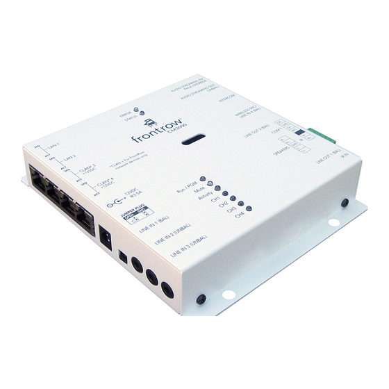
Page 6: Get Familiar With Input And Output Ports
2 Powered LAN Ports ground point in the event of ground loop hum NOTE: The Powered LAN Ports are +12V DC on Audio Input 1 and are used only for FrontRow devices 5 Audio Inputs 3 Device Power Right Side... -
Page 7: What Do You Want To Amplify? What Do You Want To Transmit And To What Device
3. What do you want to amplify? What do you want to transmit and to what device? Your CM3000 can amplify and switch a variety of audio inputs, and can control devices with serial interfaces. Now is the time to plan what you want to do. - Page 8 • Organize the network information in a spreadsheet such as the one found at http://gofrontrow.com/how-to/room-control-project-planning-template.xls:...
-
Page 9: Step 2: Configuration
Step 2: Configuration Your CM3000 has several parameters that can be configured to tell it how to communicate with other devices in an ezRoom or Conductor installation. While each installation is different most of the default parameters will be appropriate. -
Page 10: Name Your Cm3000
3. Secure your CM3000 If the project requires it you can password-protect the CM3000 configuration screens by setting Security Level to Admin after which a person can access the configuration screens only by entering the password. (If Security Level is set to None, no password is required.) -
Page 11: Set Audio Parameters
• Startup refers to the volume level when the device is powered up. 0 is lowest and 32 is highest. • The Presets can be used to send a control code that sets the CM3000 to a preset volume level. For most installations this is not used as one can send an exact volume command to a CM3000 directly. -
Page 12: Set Codec Parameters
• MIC adjusts the gain of an audio source plugged in to the Audio Streaming Input port. • Intercom adjusts the gain for intercom devices CB75 or CB85. Boost and Gain allow for adjustments of the Intercom volume levels when switching between different microphone types (such as the FrontRow CB65 or CB75). - Page 13 Other Settings • VOX Level should not need to be changed; unless you are an experienced audio engineer and are working with unusual installation requirements please leave this set at 128. • When used with a TB-13 adaptor Enable audio detect triggering enables the detection of an audio signal from a legacy (e.g., non-Conductor) paging system so as to duck other audio inputs;...
-
Page 14: Enable Networking
CM3000 is 192.168.1.103 you must use the address provided by the IT department and ensure that each device has a unique address. • The IP Subnet Mask is provided by the IT department; if the CM3000 is used as part of a Conductor system the subnet mask must be 255.255.255.0. -
Page 15: Serial Ports
7. Serial Ports • The COM Port menu specifies the COM port number that the parameters on this page apply to; the CM3000 has only one COM port. • Baud Rate specifies the data speed at which the CM3000 should communicate with the attached serial device; while 9600 and 19.2K are typical for projectors, data speeds vary by manufacturer. - Page 16 • Checking Master device tells the Conductor server that this CM3000 has a microphone and is allowed to initiate pages. This is set only when the CM3000 is part of a Conductor admin station, not when it is simply a part of the intercom system.
-
Page 17: Enter Command
Control feedback requested in the command sent will be displayed in the Receive Command field if specified within the control command. If no reply is requested Command successful will be displayed; this only means that the CM3000 successfully sent the command. In practice, the most salient feedback is gotten by observing the device itself. -
Page 18: Event Definition
11. Event Definition The CM3000 is an amplifier, an encoder/decoder for audio over IP and an IP switch, but it can also store predefined commands that are executed when certain triggers occur. The menu of commands is the same as that shown in the previous screen, and the following screen shows triggers to initiate commands. -
Page 19: Event Viewer
Note that triggers 5 and 6 represent legacy paging systems (i.e., not a Conductor system) audio start and audio stop for the Page Override feature. • Events 1 and 2 are triggered by the GPI of the CM3000 (open and close) • Events 3 and 4 are triggered from the CB75 push button if so programmed and configured •... -
Page 20: Choose File Store
13. Choose file store The set of configuration parameters created by the previous screens can be saved in a file for use with other CM3000s. In this section you would “save” a configuration file or “load” a file from a location on your computer. Some of the parameters would still need to be changed (e.g., the IP address). -
Page 21: Step 3: Physical Installation Prep
Step 3: Physical Installation Prep Nearly everything you need to install your FrontRow CM3000 is included in its shipping box, or in the shipping box of the ple- num or wall enclosure containing the CM3000. However, you will need some basic tools and materials, depending on how your classroom is built. -
Page 22: Step 4: Plan Your Installation
Student desks Windows Blu-ray Player Teacher’s desk, computer and document camera White board/ projector screen Top view of an example classroom If your CM3000 will be part of a Conductor setup, locate it close to a power source and LAN drop. -
Page 23: Step 5: Install Your Cm3000
Step 5: Install your CM3000 Connecting your CM3000 in an ezRoom installation 1. Plug the power supply jack into the 12VDC (3.5A) power socket. 2. Connect the Channel 1 mini-audio jack to the LINE IN 1 port. Any combination of ports can be used. The default jumper position for LINE IN 1 is for balance mode. - Page 24 IP addressable devices; for example, use one of the powered LAN ports (CLAN3 or CLAN4) for the CB2000 or CB6000 room control panel. (Cables aren’t provided with your CM3000.) 4. Connect the wires for the left and right speakers at the SPEAKERS terminals as shown below with the included Phoenix...
- Page 25 5. If the classroom will have an intercom, such as through Conductor, connect the network cable from the FrontRow CB75 or CB85 to the INTERCOM port. (Cable is not provided with your CM3000.) 6. If your classroom will have a FrontRow Symbio wireless voice amplification system, connect the network cable to the...
- Page 26 Insert the 3.5mm connector of a FrontRow IR emitter into the TB5 3.5mm jack, and attach the emitter surface to the IR receiver on the IR-controlled device with the adhesive tab. The emitter surface is a shade of red, and should completely cover the device’s IR receiver and be securely in place.
- Page 27 8. If your classroom has a serial commands-controlled device, connect the serial wires to the COM 1 port as show below with the included Phoenix connector. (Wires are not provided with your CM3000.) NOTE: Depending on your device you may need to switch the TX and RX wires. In a 9-pin connector the standard is to use pins 2 and 3 for TX and RX, but there is no standard as to which is which.
- Page 28 9. If your classroom is connected to the school’s analog paging system (i.e., a legacy system, not a Conductor system), your CM3000 can mute classroom audio sources when it detects a page, providing greater intelligibility and a safer environment for students and staff in the event of an emergency.
-
Page 29: Connecting Your Cm3000 In A Conductor Installation
1. Plug the power supply jack into the 12VDC (3.5A) power socket. 2. Connect the network cable for the school LAN to the LAN 1 port. (Cable isn’t provided with your CM3000.) For convenience the LAN 2 port can be used to connect the Shuttle Touch Screen display to the network. - Page 30 3. Connect the CAT 5 cable from the FrontRow CB65 microphone to the INTERCOM port of the CM3000 4. Connect the speaker output of the admin station CM3000 to the passive speakers as provided in the admin kit.
- Page 31 5. Optionally, to deliver music or other content over the school PA system, connect a source to AUDIO STREAMING IN / PAGE OVERRIDE port.
-
Page 32: Troubleshooting
Most manufacturers use pin 2 for TX and pin 3 for RX, but over 10% use the reverse. I’ve forgotten my password and need to reset the device. • Resetting your CM3000 involves the same procedure as that for many FrontRow devices: briefly shorting the COM 1 RX and TX terminals. -
Page 33: Appendix A: Control Commands For The Cm3000
Appendix A: Control commands for the CM3000... -
Page 36: Appendix B: Network Settings
Appendix B: Network Settings This section describes how to change the setting of your computer’s wired network adapter to use a fixed (or static) IP address rather than an automatically assigned address through DHCP. The screen shots for this procedure were taken from a computer running Windows 7, and while other versions and other operating systems will look different, the general procedure is identi- cal. - Page 37 3. Click on View network status and tasks. Note that your computer may be set up differently and you may see an alternate view, such as that shown below, in which case select Network and Sharing Center.
- Page 38 4. Click on Change adapter settings. Note that your computer may display different wording such as Manage Network Connections. 5. Double click on Local Area Connection.
- Page 39 7. Select Use the following IP address. In the IP address field enter 192.168.1.100. This is the static IP address to use when connecting to FrontRow networked devices. Click into the Subnet mask field; it may automatically fill in 255.255.255.0 but if...
- Page 40 8. To return your computer to its original condition where it uses DHCP, follow the same steps described above but select Obtain an IP address automatically, press the OK button and close each popup as before.
-
Page 41: Appendix D: Changing Cm3000 Line Output From Balanced To Unbalanced
The CM3000 Line outputs can be configured for balanced or unbalanced output by changing the jumper settings in side the box. As of spring 2014, FrontRow began shipping units with the line outputs set to unbalanced to work best with Audio Out wall plates for bringing audio into the classroom for PFM systems or computer input. - Page 42 Step 3: Change the jumper positions to unbalanced. This will affect both Line Out 1 and Line Out 2. Jumpers set to balanced Jumpers set to unbalanced Step 4: Replace the top and secure with the screws The best way to re-assemble the cover is to slide it over the base slightly tilted to avoid the LEDs, until the connections on the Line Out side click into the openings in the top, then carefully drop the lid down so that the LEDs fit into the openings in the top.
- Page 43 © 2014 FrontRow Calypso LLC Phonic Ear, FrontRow, Calypso and the names of Phonic Ear, Calypso, and FrontRow products are trademarks or registered trademarks of FrontRow Calypso LLC in the U.S. and other countries. 821-3001-005/Rev. C...
Need help?
Do you have a question about the CM3000 and is the answer not in the manual?
Questions and answers