
Related Manuals for Daikin RK20GV1B


Summary of Contents for Daikin RK20GV1B
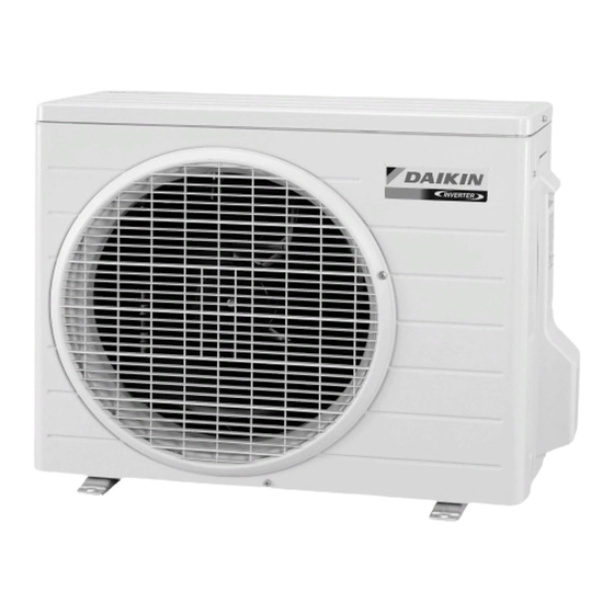
- Page 1 Si00-874 REMOVAL PROCEDURE S E R V I C E M A N U A L 2.0/2.5/3.0/3.5 kW Class Outdoor Unit Inverter Pair Type...
- Page 2 Service Manual Removal Procedure Outdoor Unit Cooling Only Heat Pump RK20GV1B ARX20GV1B RK25GV1B ARX25GV1B RK35GV1B ARX35GV1B RK20GVLT RX20GV1B RK25GVLT RX25GV1B RK30GVLT RX35GV1B RX20GVLT RX25GVLT RX30GVLT...
-
Page 3: Table Of Contents
Si00-874 Table of Contents 1. Removal of Outer Panels ................2 2. Removal of Outdoor Fan / Fan Motor .............4 3. Removal of Electrical Box / PCBs ............6 4. Removal of Sound Blankets..............14 5. Removal of Electronic Expansion Valve ASSY........16 6. Removal of Four Way Valve ..............17 7. -
Page 4: Removal Of Outer Panels
Removal of Outer Panels Si00-874 1. Removal of Outer Panels Procedure Warning Be sure to wait for 10 minutes or more after turning off all power supplies before disassembling work. Procedure Points Step 1. Appearance features (R10742) Take care not to cut your finger by the fins of the outdoor heat exchanger. - Page 5 Si00-874 Removal of Outer Panels Step Procedure Points Remove the 3 screws (right: 1 screw, left: 2 screws) and remove the top panel. Top panel Remove the 6 screws of the front panel. Front panel (R16331) Lift up the left side and unfasten the hooks.
-
Page 6: Removal Of Outdoor Fan / Fan Motor
Removal of Outdoor Fan / Fan Motor Si00-874 2. Removal of Outdoor Fan / Fan Motor Procedure Warning Be sure to wait for 10 minutes or more after turning off all power supplies before disassembling work. Procedure Points Step 1. Remove the outdoor fan. Preparation Remove the panels Remove the nut of the... - Page 7 Si00-874 Removal of Outdoor Fan / Fan Motor Step Procedure Points Release the fan motor lead wire from the hooks. (R14778) Remove the 3 screws to remove the fan motor. Fan motor (R14779) Removal Procedure...
-
Page 8: Removal Of Electrical Box / Pcbs
Removal of Electrical Box / PCBs Si00-874 3. Removal of Electrical Box / PCBs Procedure Warning Be sure to wait for 10 minutes or more after turning off all power supplies before disassembling work. Procedure Points Step 1. Remove the right side Preparation panel. - Page 9 Si00-874 Removal of Electrical Box / PCBs Step Procedure Points Remove the screw on the rear side of the right side panel. Right side panel (R17308) Remove the 4 screws on the right side panel. (R11762) Unfasten the hook on When reassembling, make Hook the rear side.
- Page 10 Removal of Electrical Box / PCBs Si00-874 Step Procedure Points 2. Remove the electrical box. [S80]: four way valve coil Disconnect the connector [S80]. [S80] (R7388) Disconnect the [S40]: overload protector connector [S40]. [S40] (R7389) Disconnect the [S20]: electronic expansion connector [S20].
- Page 11 Si00-874 Removal of Electrical Box / PCBs Step Procedure Points Release the discharge Pay attention so as not to pipe thermistor. lose the fixture for the thermistor. When reassembling, do not insert the thermistor up to the dent of fixture. Fixture Dent Discharge pipe thermistor...
- Page 12 Removal of Electrical Box / PCBs Si00-874 Step Procedure Points Lift and remove the electrical box. Electrical box (R11236) 3. Remove the main PCB. 1: black, upper 2: white, lower Remove the screw on 3: red, upper the terminal board. ) : green / yellow, lower Terminal board Cut the clamp.
- Page 13 Si00-874 Removal of Electrical Box / PCBs Step Procedure Points Remove the 3 screws to remove the reactor. Reactor (R15862) Disconnect the [S90]: thermistors connector [S90]. [S90] (R15863) Remove the 6 screws. Main PCB (R15864) Disconnect the 3 [S10] [HL3] [HN3]: filter PCB [S10] connectors [S10] [HL3] [HN3].
- Page 14 Removal of Electrical Box / PCBs Si00-874 Step Procedure Points Unfasten the 2 hooks. Lift and remove the main PCB. (R15869) 4. Remove the filter PCB. Cut the clamp. (R14813) Release the harnesses from the hooks. (R14814) (R18752) Removal Procedure...
- Page 15 Si00-874 Removal of Electrical Box / PCBs Step Procedure Points Remove the screw. (R14816) Unfasten the 2 hooks. (R14817) Release the harnesses. (R14818) Remove the filter PCB. Filter PCB (R14819) Removal Procedure...
-
Page 16: Removal Of Sound Blankets
Removal of Sound Blankets Si00-874 4. Removal of Sound Blankets Procedure Warning Be sure to wait for 10 minutes or more after turning off all power supplies before disassembling work. Procedure Points Step 1. Remove the partition Some models have 3 plate. - Page 17 Si00-874 Removal of Sound Blankets Step Procedure Points 2. Remove the sound Since the piping ports on the blankets. sound blanket are torn easily, remove the blanket Lift and remove the carefully. sound blanket (top). The design of the sound blankets varies depending on the model.
-
Page 18: Removal Of Electronic Expansion Valve Assy
Removal of Electronic Expansion Valve ASSY Si00-874 5. Removal of Electronic Expansion Valve ASSY Procedure Warning Be sure to wait for 10 minutes or more after turning off all power supplies before disassembling work. Step Procedure Points Pull out the electronic expansion valve coil. -
Page 19: Removal Of Four Way Valve
Si00-874 Removal of Four Way Valve 6. Removal of Four Way Valve Procedure Warning Be sure to wait for 10 minutes or more after turning off all power supplies before disassembling work. Step Procedure Points 1. Remove the peripheries. The cooling only models do Remove the terminal not have a four way valve. - Page 20 Removal of Four Way Valve Si00-874 Step Procedure Points Pull out the electronic expansion valve coil. Electronic expansion valve coil (R11798) Remove the putty. Warning Be careful not to get yourself burnt with the pipes and other parts that are heated by the gas brazing machine.
-
Page 21: Removal Of Compressor
Si00-874 Removal of Compressor 7. Removal of Compressor Procedure Warning Be sure to wait for 10 minutes or more after turning off all power supplies before disassembling work. Procedure Points Step 1. Remove the peripheries. Warning Remove the four way Be careful not to get yourself valve, the terminal burnt with the pipes and other... - Page 22 Revision History Month / Year Version Revised contents 06 / 2013 Si00-874 First edition...
- Page 23 Improper installation can result in water or refrigerant leakage, electrical shock, fire or explosion. Use only those parts and accessories supplied or specified by Daikin. Ask a qualified installer or contractor to install those parts and accessories. Use of unauthorised parts and accessories or improper installation of parts and accessories can result in water or refrigerant leakage, electrical shock, fire or explosion.
Need help?
Do you have a question about the RK20GV1B and is the answer not in the manual?
Questions and answers